Solution Finder
SOLUTION FINDER

La vostra guida nel mondo dei prodotti Rösler

Con pochi clic troverete la macchina giusta per le vostre esigenze!

Risultati: 237 Articolo

A Holistic Look at Automated Blasting in the Modern Metal Fabrication Shop

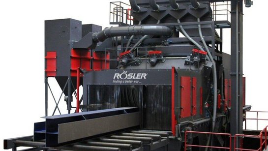
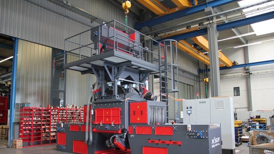
Written by Rosler CEO Bernhard Kerschbaum, this article was originally published in The Fabricator . Modern metal fabrication operations aren’t like the fab shops of old. Many are clean, well lit, with employees working in fresh, filtered air. Yes, some operations in fabrication are, well, just plain dirty—and manual blasting is a prime example. The work isn’t pleasant, requires protective gear, and if the booths aren’t maintained or set up properly, they can constrain workflow in a serious way. Options in blasting automation abound, but before diving into all that technological wizardry, try laying some groundwork by answering a fundamental question: What must the blasting operation accomplish? Shot Blasting Versus Shot Peening Shot blasting (or just “blasting” if using a different media other than shot) prepares a metal surface while shot peening aims to change the metal’s properties (see Figure 1 ). Certain aerospace applications require precise levels of stress relief (or other changes to material properties), and they use specialized shot-peening technologies to achieve it. Precision shot peening of landing gears is a prime example, with the process optimizing surface stresses, eliminating microcracks and the stress risers around them. Most metal fabricators employ blast cleaning for the vast majority of their applications, cleaning and preparing a metal surface for the next manufacturing step, usually painting. If a beam or plate isn’t blasted correctly, paint won’t adhere properly. However, some fabrication operations do employ a kind of peening—not as precise as high-end peening applications, but it’s peening nonetheless, with the media impacting the surface and causing compressive stresses that aim to change the material’s properties. Imagine fabricating a bowl that will be used in a high-vibratory setting. The welds within those bowls need a certain amount of stress relief, and shot peening helps accomplish this. To ensure adequate stress relief for the welds, the application might choose to use large shot, which can have a peening effect that penetrates deeper into the surface. Alternatively, the operation might choose to use the same shot that it uses for blast cleaning applications, though extending the cycle time to achieve the required peening effect within the part. When to Blast? Again, the majority of fabricators need to prepare a workpiece surface for a downstream operations like painting—so, they’re blasting (not peening). The higher quality the end finish is, the more important surface preparation becomes. Put another way, a high-quality, highly consistent coating requires a high-quality surface preparation. An automotive car panel requires very different surface prep compared to a structural beam. Where in the manufacturing sequence does it make the most sense to blast? Are cut plates being blasted to prepare them for downstream processes, or will the completed fabrication be blasted after bending and welding? Applying blasting to incoming material might seem counterintuitive, especially if welds need to be blasted anyway. After all, most operations that employ blasting do so just before it enters the final coating process. Still, blasting needn’t always occur at the end of the value stream. Sometimes, cleaner material coming into the shop can help downstream processes like cutting and welding, and it might help streamline the final finishing operation significantly. Some operations might choose to automate the blasting of incoming material yet keep the final blasting of welds manual, before the work enters the final coating process. The operation isn’t entirely automated, but because incoming material is clean, overall throughput rises dramatically, and time and labor required for manually blasting the fabricated parts is significantly reduced. Coating also doesn’t necessarily need to occur at the very end of production. For instance, some shipyards blast incoming plate, prime them with a weldable primer, then weld. Afterward, the work is blasted again—but only the welded seams. For large workpieces especially, such a manufacturing sequence helps streamline the overall operation significantly. Blasting Variables The industry has various standards (such as those from SSPC and NACE) to help fabricators assess the surface condition of material. The cleaner the material, the less aggressively you need to blast it, and the less aggressive blast media you need to use to achieve the desired finish. When working with plate with significant rust, shot might need to be larger, or the application might call for grit, which is angular. Round shot usually produces a finer finish than grit, but grit might be required to produce a rougher surface profile for adequate adhesion for a thick coat of paint. FIGURE 1. For fabricators requiring shot peening, for weld stress relief or any other application involving a change in material properties, maintaining the proper mix of media is critical. Fractured and undersized media must be continuously and consistently removed from the peening system. Consider the condition of raw stock and the final finish required—that is, what’s delivered versus the final surface finish you need to achieve before the product ships. The difference between the incoming and outgoing material quality determines the blasting throughput. The greater the difference in quality (that is, very rough to a fine finish), the longer the blasting will take. Some applications also might require several blasting stages, the first to clean and another secondary stage, using finer blast media to dial in the surface’s paint adhesion characteristics. “Speed” in blasting can be defined several ways. First, how much shot needs to hit the surface at a given time, and how often the shot needs to strike to remove rust and prepare the surface as needed? The more rust a workpiece has, the more shot it will require. One turbine might throw 500 lbs./min. of shot at a slow-moving workpiece, to ensure enough shot strikes the surface enough times to create the surface finish needed. Alternatively, a system can have multiple blast wheels, positioned one after the other, that throw (altogether) 1,500 lbs./min. to the surface, which allows parts to travel three times as fast. There’s a limit to this, of course. Throw too much shot, and the shot media begins to ricochet within the system, which in turn creates all sorts of inconsistencies. Thrown at a high enough volume, the blast media itself loses its effectiveness. Several variables control blast intensity. An operation can adjust the feed valves to control how much media flows onto the turbine. Alternatively, an operation might slow the turbine speed, so the blast media itself hits the part at a slower velocity. An application has an optimal exit velocity; too low, and the media isn’t effective (for instance, it fails to knock off surface rust); too high can cause other issues, like warping, especially for very thin workpieces. Another variable involves blast media size distribution. Automated systems have recycling systems that separate the blast media from the removed rust and debris. The recycling system itself is extremely critical; if it’s not operating properly, the blast media won’t be consistent, which can lead to paint adhesion and other challenges. Shot becomes smaller and smaller as it’s recycled. The blast media recycling system must be monitored to ensure enough fresh shot or other media is added to the mix, and that the screening system (which evacuates fine particles) is working properly. The procedure isn’t complicated. Operators essentially take a blast media sample and send it through several specially designed sieves, so they can see the coarseness distribution and any debris or contaminants that might be present. Anatomy of a Blast Machine Blast machines carry the parts through the blast stream, collecting as little media as possible on the part while also exposing every surface that needs to be blasted. The blast stream the turbine throws has a “hot spot” near the center, an area where the blast media carries the most energy. This in turn governs the optimal position of the turbines (see Figure 2 ). For instance, a blast machine that processes plate requires even distribution of blasting across the surface, and if those hot spots in each blast stream don’t overlap, the plate might end up with “stripes” in areas exposed to less blast media. These basics form the foundation of any blast machine design. A popular design for metal fabrication includes roller-type machines, where widely spaced rollers (see Figure 3 ) carry plate or beams into a machine, where it’s blasted from multiple directions. Placement of the turbine is key (see Figure 4 ). Some machines might place blast turbines a certain distance away to accept, for example, various beam geometries. The arrangement might not be as efficient for plate as a machine with turbines placed closer to the work, but the arrangement does offer flexibility—that is, the system can process both flat plate and beams of various shapes and sizes. FIGURE 2. Turbines emit overlapping blast streams to ensure all workpieces receive sufficient coverage. Again, when the work is blasted plays a role too. That flexible machine might blast raw plate to clean and prepare it for downstream processing, then blast the assembly after welding. A shop might employ this strategy because of blast media access issues (that is, a machine’s blast media can’t access all surfaces of the assembled product), or because welding requires clean surfaces that the blasting process produces. Alternatively, the company might choose to “blast twice”—both incoming stock and welded products—because it’s still the fastest, most efficient way to process the work. Cleaning raw stock as it comes in streamlines downstream operations. And because parts were already cleaned, blasting of the welded assembly takes less time. Which machine a fabricator chooses depends on the application requirements, including the part geometry. Flat parts or beams might be adequately blasted on a roller-type machine, while booms, buckets, or other complex shapes might call for a hanger-type or spinner-hanger-type machine. A bucket sent through a roller machine might start accumulating shot on its surface, which prevents the shot from hitting the surface with sufficient energy. In this case, a spinner-hanger blast machine, where a ring of blast turbines around a hung part that’s spinning, might be able to access all surfaces while still allowing the spent shot to fall from the part. The manual blast room’s principal benefit is operator access. The operator can blast all surfaces and brush off accumulated shot as needed. An automated system might not have this flexibility. At the same time, blast media from a turbine within an automated machine has much more energy than blast media from a manual gun. That energy can reduce the media buildup significantly. So, while a manual operator might be able to blast complex, challenging geometries, he also might have to brush off accumulated media more frequently. (Note: manual touchup blasting can be integrated into an automatic blast machine, such as a hanger-type machine. In that case, the operator suits up and blasts the part with a manual blast wand inside of the disabled blast machine.) On the other end of the spectrum, some blasting technologies offer complete automation—and not just of the entire blasting process. Some plate and beam blasting systems connect directly to a painting system (see Figure 5 ). Again, these help minimize the required surface prep later in the value stream. At the steel supplier or at the fabricator itself, beams and plates are blasted then immediately coated with a weldable primer. Such systems also can come with a cleaning station before blasting—especially useful for structural fabricators that store their material outside. That station removes the loose debris (like dirt, snow, and leaves) before the beams enter the blasting station. After blasting, the work passes through a cleaning station with brushes and air blowers, which remove any remaining shot or other debris before the pieces flow to painting and drying. Throughput for these systems depends on the material condition entering the machine as well as the painting requirements like thickness, consistency, and curing time. Designers of such systems have optimal throughput in mind. If curing time takes longer, then the blasting system could be altered to run slower (slower turbines, less media, or a combination of both). At the same time, not every workpiece need be sent through the painting system. For instance, a fabricator that cambers beams or forms plates downstream wouldn’t want to paint those pieces upstream, so those workpieces that undergo those processes could simply be blasted and then quickly sent through the idle painting system, then on to cambering or forming. Again, it’s about overall throughput, not the “local efficiency” of a specific blasting or painting process. Yes, blasting might take a little longer when coupled with painting, and the painting system might not be used for every beam. But linking painting directly to blasting boosts overall flow and minimizes work-in-process—both of which represent huge time savings. The result: The shop blasts and paints more material in less time using fewer resources. About the Entire Value Stream In applications with widely varying or complex part geometries, a fabricator might choose to partially automate blasting, with a machine blasting 80% or more of the material surface and a manual operator blasting the remaining 20%. Automating the entire process is, of course, ideal for many applications—but not all. The idea is to implement automated blasting where it can be most effective. In other situations, the operator might need only to blow blast media off. Certain hanger-type systems, for instance, have a designated cleaning station where operators, for parts that require it, can perform a final cleaning before the part moves on to the next stage (see Figure 6 ). FIGURE 3. Widely spaced rollers carry plate, beams, or similar workpieces through into the machine. The aim is to streamline the entire value stream, and this extends up to material purchasing. A fabricator could buy more expensive material that requires less blasting or no blasting at all, or it could buy less expensive material that requires significant blasting and surface preparation. However, what if the welds require blasting regardless of material quality? As long as application requirements can be met, it might make more sense to purchase the less expensive raw stock, spend more time blasting, and yet (thanks to less expensive material) save money overall. A high-volume fabricator might even choose to bring an automated blasting and painting line in-house, not only because it increases throughput, but also because it allows the operation to purchase less expensive material and gain greater control over material surface quality—depending, of course, on the final application requirements. Some structural beam processing operations have effectively automated their entire flow, from blasting to cutting, painting, then loading directly onto trucks. In at least one European structural steel fabricator, one operator sits in an air-conditioned room and controls the entire operation. His main job is to monitor equipment and flag maintenance personnel should a problem arise—be it extra vibration on a blast turbine (detected through sensors), a blade vibration issue at the band saws, or anything else. Developing such systems didn’t occur overnight, and it didn’t happen by analyzing specific processes in isolation. Considering the entire value chain is key, including linkage with enterprise resource planning as well as the potential of AI-driven predictive maintenance. When this happens, fabricators often find they can take automation to new heights. FIGURE 4. A blast machine's turbine wheels (three of them just above the work entrance) are placed to accept a variety of workpiece geometries. FIGURE 5. In this setup, beams or plates are blasted, cleaned, then flow directly to painting for a weldable primer. FIGURE 6. Some systems offer automated blasting together with a manual cleaning station.

Partnership Provides Excellent Finish for Deep-Drawn Medical Components

Deep-drawn functional components are increasingly being utilized in the production of medical and pharmaceutical products. To meet the strict standards for manufacturing and quality management in the field of surface finishing, Hubert StĂŒken GmbH & Co. KG has relied on mass finishing solutions and consumables from Rosler for more than 30 years. Founded in 1931, Hubert StĂŒken GmbH & Co. KG is a family-owned business with manufacturing operations at five locations in Europe, Asia, and the United States. Its product range includes stamped and bent parts, plastic-coated components, and complex assemblies. Rosler works with StĂŒken Medical , the company’s medical business division which focuses on medical and pharmaceutical engineering, to meet the increasing demand for deep-drawn metal components. Andreas Hellman, Manager of the ISO 13485-certified business division, explained, “Components used in the field of medical and pharmaceutical engineering must meet strict quality standards. The same strict standards apply also to the actual production operations. For this reason, we have pooled the required know-how for the development and production of such precision components at StĂŒken Medical.” The Situation Among other items, this division produces complex housings and assemblies, valves, extremely precise micro parts, and primary packaging. These components are made from metals suitable for deep drawing, including stainless steel, aluminum, and titanium. To meet the strict quality standards in the medical and pharmaceutical industry, the company utilizes multi-stage cleaning systems and operates two class 7 cleanrooms. Its research and development department, located at the corporate headquarters in Rinteln, Germany, continuously explores the possibilities to expand the range of processes and materials. “For many of our customers, we are a development partner,” Hellmann said. “To perfectly adapt new products to their intended use, we are not only working with our customers but are also cooperating with partners from various technological sectors.” The Solution When it comes to issues around surface finishing that can be resolved by mass finishing, the company has relied on Rosler’s experience and know-how for more than 30 years. “Our long partnership is based on the excellent quality and reliability of Rosler equipment and consumables,” Hellmann said. “This helps us to ensure that the required results are achieved in a consistent manner.” Dirk Schulz, Project Engineer at StĂŒken, agreed. “When it comes to the joint development of finishing processes, we especially value Rosler’s flexibility and expertise,” he said. “In this respect, our access to the Customer Experience Center in Untermerzbach is extremely valuable. “Rosler also supports us with documentation and equipment details required for machinery and processes that must be qualified and validated in line with ISO 13485,” Schulz said. At its manufacturing locations around the world, this deep-drawing specialist uses 15 rotary vibrators and 10 centrifugal disk finishing machines for its finishing operations. StĂŒken Medical also operates 18 process water centrifuges for eco-friendly and reliable cleaning and recycling of the process water. Rotary vibratory machine with work pieces in the media mix The Requirements The deep-drawn components are generally characterized by an extensive degree of material shaping, complex geometries, and extremely small dimensions requiring high dimensional accuracy and especially demanding specifications for deburring , edge radiusing , and polishing of external and internal work piece areas. Equally challenging are the surface roughness and surface quality requirements. “On the one hand, we must ensure that all pieces within a work piece batch receive the same high-quality surface finish. On the other hand, the work pieces must not be damaged or deformed,” Schulz said. “Last but not least, after completion of the finishing process, the work pieces and media must be reliably separated. A carry-over of the work pieces and/or media into the next batch must be prevented at all costs,” he added. In conjunction with polishing jobs, the work piece surface must frequently be marked with a UDI code. Fully meeting these specifications requires finishing processes that are precisely tailored to the respective work pieces as well as carefully adapted equipment and consumables. Conducting special feasibility studies is often required to determine system parameters. Deep drawn component made by StĂŒken The process for radiusing the edges of 0.8 in (20 mm) stainless steel housings for a medical device was developed in close cooperation with StĂŒken. This delicate housing’s large surface area in combination with extremely thin walls posed a challenge. To remove sufficient material at the edges, a high processing intensity that could be tightly controlled was required to prevent any deformation. The Cooperation The Customer Experience Center at Rosler is equipped with ultra-modern machines capable of running a wide variety of different finishing processes and conducting trials to define the most suitable equipment technology under actual production conditions. During such development processes, the processing bowl of standard machines must be frequently modified, sometimes involving substantial engineering changes. For this project, the comprehensive mass finishing experience at StĂŒken was a valuable source of ideas. To guarantee a reliable and complete separation of the finished work pieces from the media, the finishing equipment for StĂŒken Medical required a few changes in the separation process. Another goal of processing trials is the determination of the optimal media shape and type ( ceramic or plastic ) for the finishing task at hand. In order to achieve consistently good surface finishes, very often the media must have extremely tight dimensional tolerances. Deep drawn component made by StĂŒken All ceramic and plastic media are produced at Rosler in compliance with the highest ecological standards. With over 15,000 different products, the media, compounds, and process water cleaning agents Rosler offers are by far the largest range of mass finishing consumables in the world. A key factor in the development of successful finishing processes is the perfect interplay between the right equipment technology and the right consumables (media and compound). Generally, the best results are achieved by close cooperation with the customer. The Rosler Way Decades of experience and the ability to design, service, and maintain machines as well as provide the consumables and accessories required to get the finish you require make Rosler a well-rounded, single source for surface finishing expertise. Contact us to discuss your mass finishing needs.

Interlinked Mass Finishing and Cleaning Systems Half Processing Time

Because of a positive experience with four continuous flow washing machines operating at its headquarters, VIA OberflĂ€chentechnik (VIA) decided to work with Rosler for a comprehensive mass finishing and cleaning operation. The resulting interlinked system meets the most demanding cleanliness specifications while achieving significant cycle time reductions and cost savings and providing a high degree of operational flexibility. The Situation Headquartered in Lennestadt, Germany, VIA sought an integrated solution for de-oiling, mass finishing, and deep cleaning of stamped and formed parts. Since its founding in 1996, the job shop company has been one of the leading work piece cleaning specialists in Europe. Its three production locations process automotive and other components. An in-house laboratory ensures that the treated work pieces are in full compliance with the specified cleanliness demands. Depending on the stringency of the customer requirements, some products are even packed in a dedicated cleanroom. After extensive cleaning trials with pilot production runs, VIA received a large order from an automotive supplier for volume cleaning of clutch carriers. The company's existing cleaning and mass finishing capacities were no longer sufficient and had to be further expanded. Rosler mass finishing system The Solution “Right from the project start, it was clear that we would purchase a new mass finishing system from Rosler," said Kai Lechner, Manager at VIA. "We were not certain about buying the water-based cleaning systems from the same supplier, but after inspecting a fully automatic combined mass finishing/cleaning system that has been successfully running at an automotive supplier for several years, we decided to purchase the complete package from one supplier, namely Rosler," he said. Utilizing the Rosler team as the single supplier and integrator for the interlinked system provided numerous benefits. Since Rosler not only produces the finishing equipment, but also the washing systems, our extensive experience in integrating robotics allowed us to provide a turnkey solution for VIA. Based on prior successful partnerships with Rosler, VIA also knew we had the expertise and experience to be responsible for the process, minimizing the need for coordinating with different vendors and providing one point of contact for a complex project. VIA's new line consists of two cleaning units, a linear continuous flow vibratory inline system , and an automatic process water cleaning system ; all supplied by Rosler. The company also purchases its grinding media as well as all cleaning and finishing compounds from Rosler. “For us, it is a lot easier to deal with one partner who takes care of everything including service and maintenance," Lechner said. The Process For the de-oiling stage, the clutch carriers are manually placed on the feeding conveyor of the compact spray-rinse washing machine. During the 6-second cycle, they pass through two separate cleaning zones and one blow-off station. Filtration units and a coalescence separator increase the clean liquid systems' uptime utilized in the initial step. A single media is used in the various cleaning processes which allows the work pieces to be directly transferred into the mass finishing machine without a drying step. Deburring and edge radiusing take place in the linear continuous flow vibrator, type R 650/6600 DA. Process water used in the machine is continuously cleaned by an integrated Z1000 centrifuge equipped with fully automatic sludge discharge. A vibratory separation unit transfers work pieces from the mass finishing machine to a feeding conveyor and the deep cleaning unit parts washing system. To ensure that the work pieces meet the stringent cleanliness requirements of no metallic particles > 600 ”m, the carriers are manually positioned prior to entering the deep cleaning unit. Work pieces then pass through a cleaning zone followed by a rinsing and passivation zone. In these zones, the parts are sprayed with a cleaning solution from above and below. The pressure and volume of the water flow from the upper and lower spray nozzles can be separately adjusted, and the various parameters can be stored as individual programs in the equipment controls. After passing through a drying zone, the work pieces are discharged. Process Advantages The operational flexibility of the system allows VIA to utilize the different modules in any conceivable combination. The combined cleaning/finishing system also allows the processing of other work pieces with similar size and shape. Compared to the pilot production's cleaning process and its numerous manual operations, the new system cuts the processing time in half. “A big advantage is that after an unplanned delivery stop by the customer, we can resume production much more quickly and can supply the OEM with cleaned work pieces in extremely short lead times,” Lechner said. The interlinked equipment concept also yielded considerable cost savings by reducing the required manpower for operating the system. It also greatly improved the working environment for employees since they no longer need to move the part bins between different machines, saving them time and effort. Decades of experience and the ability to design, service, and maintain machines as well as provide the consumables and accessories needed to get the finish you require make Rosler a well-rounded, single source for surface finishing expertise. Contact us to discuss your mass finishing needs.

Herzensangelegenheit Mitarbeiter-Ehrung – Rösler feiert endlich wieder im großen Rahmen

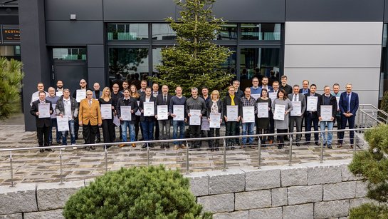
Im Jahr 1982 wurde Helmut Kohl Bundeskanzler der Bundesrepublik Deutschland, in Erlangen wurde das erste Retortenbaby des Landes geboren, und das US-Nachrichtenmagazin „Time“ wĂ€hlte den Computer zur „Maschine des Jahres“. Alles entscheidende Ereignisse, die den Lauf der Welt maßgeblich beeinflusst haben. FĂŒr Maria Zillig und Thomas Eberth war das Jahr 1982 aber noch aus einem anderen Grund besonders einschneidend: Es war das Jahr, in dem sie ihre Ausbildung zur Industriekauffrau und zum Industriekaufmann begonnen haben. Und zwar bei der Rösler OberflĂ€chentechnik GmbH in Memmelsdorf / Untermerzbach beziehungsweise Hausen. Dort arbeiten sie auch heute noch. Ganze 40 Jahre spĂ€ter. Genauso wie ihr Kollege Detlef Griebel, der ebenfalls seit 1982 bei „seinem“ Rösler beschĂ€ftigt ist. Einem Unternehmen so lange die Treue zu halten ist alles andere als selbstverstĂ€ndlich. Deshalb hat die Rösler OberflĂ€chentechnik GmbH diese, und 39 weitere langjĂ€hrige Mitarbeiter, jetzt im feierlichen Rahmen fĂŒr ihre lange Unternehmenszugehörigkeit geehrt. FĂŒr den GeschĂ€ftsfĂŒhrenden Gesellschafter Stephan Rösler ist die jĂ€hrliche Ehrungsfeier eine echte Herzensangelegenheit. In diesem Jahr ist sie es gleich aus mehreren GrĂŒnden: Nachdem die Ehrungen in den letzten Jahren aufgrund der Corona-BeschrĂ€nkungen nur im kleinen Kreise stattfinden konnten, darf in diesem Jahr zum ersten Mal wieder im großen Rahmen gefeiert werden: Im neuen Rösler Betriebsrestaurant, welches 2021 am Standort Memmelsdorf / Untermerzbach eröffnet wurde. Bei der feierlichen Ehrung der verdienten Mitarbeiter bekam Stephan Rösler in diesem Jahr UnterstĂŒtzung von seinen beiden GeschĂ€ftsfĂŒhrerkollegen Volker Löhnert und Oliver GrĂŒn. Letzterer wurde selbst fĂŒr seine zehnjĂ€hrige Betriebszugehörigkeit ausgezeichnet. Die Rösler OberflĂ€chentechnik GmbH gratuliert 
 zum 40-jĂ€hrigen BetriebsjubilĂ€um: im Werk Memmelsdorf: Maria Zillig und Thomas Eberth. Beide sind dem Unternehmen nicht nur im selben Jahr, sondern als Lehrlinge auch am gleichen Tag beigetreten. Im Werk Hausen wird Detlef Griebel fĂŒr vier Jahrzehnte Treue geehrt. 
 zum 25-jĂ€hrigen BetriebsjubilĂ€um: Eduard Fischer, Andreas Hentschel, Mario Jakob, Ralf MĂŒller, Waldemar Riwe, Folkert Rothe, Steffen Schwab, Jens Siebensohn, Gerald Weiß, Katja Wohnig, Uwe Zörkler – alle tĂ€tig im Werk Memmelsdorf – sowie Ernst Hoffer, Peter Leipert, Rainer Schindhelm und Alexander Schröder im Werk Hausen. 
 zum 10-jĂ€hrigen BetriebsjubilĂ€um: im Werk Memmelsdorf: Norbert Wolf Dicker, German Gerstenlauer, Tim Gleichmann, Susanne Henkel, Christian Höhn, Martin Hopf, Kevin Kern, Kathrin Knöferl, Wolfgang Kroner, Marcus Mannel, Andreas Merz, Marco Schmittwolf, Arno Schneider, Holger SchwĂ€mmlein, Dominik Sperlich, RenĂ© StĂŒllein, Sven Trier, Udo Weierich, Jennifer Weinland und Katja Weis sowie Katrin Fuchs, Oliver GrĂŒn, Ingrid Vetter und Yvonne Wagner im Werk Hausen. Nach langjĂ€hrigem verdienstvollen Einsatz wurden Reiner Allert, Gerhard Edelmann, Uwe Fleischmann, Herwig Heiser, Imelda Hellmuth, Carola Jankowski, Wolfgang Panzer, Fredi Spangel, Martin Trutz, Theo Wirsching sowie Oswald Zöttlein in den Ruhestand verabschiedet. Kurs halten im Krisenjahr: Rösler hĂ€lt an langfristigen Zielen fest Es war ein schwieriges Jahr mit vielen UnwĂ€gbarkeiten – dieses Fazit zog der GeschĂ€ftsfĂŒhrende Gesellschafter der Rösler OberflĂ€chentechnik GmbH, Stephan Rösler, in seinem traditionellen Weihnachtsgruß an die Belegschaft. Man sei in den ersten drei Monaten gut gestartet, der Ukraine-Krieg habe dann aber vieles verĂ€ndert – und die aufgrund der Corona-Krise ohnehin schon schwierige Lage an den BeschaffungsmĂ€rkten zusĂ€tzlich verschĂ€rft. Weitere Schwierigkeiten wie die Kostenentwicklung blieben aktuell, obendrauf kam noch die Energiethematik. Das im MĂ€rz 2022 abgelaufene GeschĂ€ftsjahr konnte die Rösler OberflĂ€chentechnik GmbH zwar erfreulich mit einem unkonsolidierten Gruppenumsatz von rund 273,9 Mio. € und somit einem Gruppenplus von rund 16 Prozent abschließen und so die durch die Pandemie verursachte Umsatzdelle aus dem vorangegangenen GeschĂ€ftsjahr hinter sich lassen. Die Prognosen fĂŒr das laufende GeschĂ€ftsjahr geben aber ein uneinheitliches Bild ab: So werden die Verfahrensmittel, Ersatzteil- und Serviceleistungen zwar weiterhin auf stabilem Niveau nachgefragt. Das NeumaschinengeschĂ€ft gestaltet sich allerdings schwieriger: Der russische Markt ist durch die Embargobestimmungen weggebrochen, außerdem ist durch die weltwirtschaftlichen Rahmenbedingungen insbesondere bei Großprojekten eine ZurĂŒckhaltung bei Investitionen festzustellen. Aus diesem Grund wird der Auftragseingang im Neumaschinenbereich zunĂ€chst unterhalb der Planungen liegen. Auch aufgrund einer Vielzahl getroffener Maßnahmen habe die Rösler OberflĂ€chentechnik GmbH die zahlreichen Herausforderungen bisher aber „ganz gut bewĂ€ltigt“, so Stephan Rösler weiter. An seiner langfristigen Ausrichtung gemĂ€ĂŸ der Firmenphilosophie Mission & Vision wolle das Unternehmen festhalten, zudem habe man 2022 trotz aller Schwierigkeiten einige wegweisende Projekte auf den Weg gebracht. Beispielsweise die Rösler Innowelt, ein umfassendes Konzept zur Umstrukturierung und Modernisierung fast des kompletten BĂŒrobestandes am Standort Memmelsdorf / Untermerzbach. Langfristig erhoffe er sich auch durch zahlreiche Produktneu- und Weiterentwicklungen, die die Rösler Firmengruppe in den letzten Monaten auf den Weg gebracht habe, weitere StĂ€rke, so Stephan Rösler. Im abgelaufenen GeschĂ€ftsjahr wurden ca. 5,6 Mio. € am Standort Memmelsdorf investiert und auch im laufenden Jahr werden weitere Investitionen in zukunftsorientierte Projekte an den deutschen Produktionsstandorten erfolgen. Seinen Mitarbeitern dankte der GeschĂ€ftsfĂŒhrende Gesellschafter fĂŒr die tatkrĂ€ftige UnterstĂŒtzung und LoyalitĂ€t im vergangenen Jahr. Trotz aller Schwierigkeiten konnte allen BeschĂ€ftigten das Weihnachtsgeld in voller Höhe ausgezahlt werden. Ein starkes Zeichen zum Ende eines Jahres, das aus vielerlei GrĂŒnden getrost als sehr schwierig bezeichnet werden darf.
wire mesh belt machine

Perfect de-flashing and dedusting of duroplast and thermoplast components at the production rate of the injection molding machine

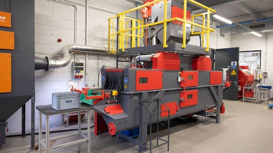
Ever since ROS GmbH & Co KG was founded in 1926 the processing of plastic materials was always at the center of the company’s activities. Initially named Press plant ROS, the company now has a nearly 100 years old tradition in this field. Today the private business, managed by third generation family members, is a high-end partner for technically demanding injection molded components made from duroplast and thermoplast materials including polyphenylene sulfide (PPS). Product development, tool making, and production take place at the company’s headquarters in Coburg, Germany. An additional manufacturing plant is located in Ummerstadt in the German state of Thuringia. For removing the flashes on the components created by the manufacturing process the company has been working with Rösler shot blast equipment since 2006. Increase of the de-flashing shot blasting capacity JĂŒrgen BĂ€r, responsible for planning in the industrial engineering department at ROS in Coburg explains: „The demand for plastic components substituting metal parts, for example in thermo management systems for the automobile industry, has been rapidly growing. In 2021 this forced us to increase our shot blasting capacity at both our manufacturing locations. The plastic components reduce the overall weight of the cars and, therefore, help to reduce CO2 emissions. In addition, we received large orders for duroplast pre-formed components, among others from a leading manufacturer of garden tools“. After discussions with four suppliers of shot blast equipment the customer chose the wire mesh belt machine RSAB 470 and the swing satellite table machine RWS 1200 from Rösler. JĂŒrgen BĂ€r continues: „Deciding factors for choosing Rösler were our good experience with the shot blast machines we have been using for a long time, the compact, space-saving and sturdy equipment design and Rösler’s comprehensive knowledge in the field of plastic de-flashing. Moreover, we needed the continuous flow shot blast machine quickly. Rösler generously supplied a machine from their customer experience center within a few days“. Consistent and energy-efficient de-flashing in the tempering frame The flexible high-capacity shot blast machine RSAB 470 at the Coburg location is used for de-flashing of components made from duroplast and the high-performance thermoplast PPS-GF materials. After de-flashing the components undergo a tempering treatment. For this purpose, the components are placed on special frames. Normally the work pieces are placed individually on the wire mesh belt. To streamline the material handling operation and eliminate this time-consuming step, Rösler adapted the standard work piece transport system of the shot blast machine to the workflow at ROS. This re-design now allows placing the raw components on the tempering frames immediately after the injection molding process. The work pieces on the frames are then passing through the shot blast machine for the de-flashing operation and can, thus, be directly transferred to the tempering station. Four turbines, specially designed for plastic de-flashing and placed above and below the wire mesh belt, ensure consistent shot blasting results. This turbine arrangement allows throwing the media consisting of polyamide grains with a diameter of 1 mm onto the work pieces from above and below. Compared to the normally utilized suction air blast systems the turbines, equipped with electric drives, are considerably more energy efficient. JĂŒrgen BĂ€r adds: „Not only our certification per DIN EN 50001 demands a reduction of our energy consumption, but energy savings are also necessary to save costs and for reasons of sustainability“. A blast media flow control with automatic media replenishment ensures that there is always sufficient blast media available in optimal quality. The shot blast machine is equipped with numerous technical features such as the anti-static compound dosing system with automatic compound replenishment, the efficient air extraction from the blast chamber, the dual step parts cleaning system in the outlet zone and the effective blast media cleaning system with screen and air wash separator. All these features guarantee that the components coming out of the shot blast machine are perfectly de-flashed and absolutely clean. Since the plastic materials used at ROS and the polyamide blast media can cause explosive dust, the shot blast machines were equipped with special, ATEX-compliant filter systems. Fully automatic and sustainable de-flashing of single work pieces The swing satellite table machine RWS 1200 was installed to increase the shot blasting capacity at the plant in Ummerstadt. It is used for de-flashing components made from PPS-GF and outer dimensions of up to 163 mm. In line with the production cycle of the injection molding machine up to four work pieces are de-flashed simultaneously within a processing time of 40 seconds. The RWS 1200 has two chambers, equipped with four rotary satellite stations per chamber and each satellite holding one work piece. This clever design allows to unload/load work pieces in one chamber, while the work pieces in the other chamber are processed. Unproductive idle times are, therefore, minimized. One energy-efficient blast turbine throws the media onto the work pieces placed on the rotary satellite stations arranged in the shape of a diamond. The satellites are not only rotating but, depending on the work piece geometry, can also be stopped at a certain angle. Work piece areas that cannot be reached by the media thrown by the turbine, are cleaned with special air blast nozzles. This suction air blast system is equipped with pressure control and a vertically moveable nozzle holder ensuring precise de-flashing. In addition to the vertical movement a linear positioning system allows to place the nozzles precisely in front of the work pieces. The nozzles are working in either oscillating or static mode. „To minimize the usage of compressed air, we are working with work piece specific PLC processing programs“, concludes JĂŒrgen BĂ€r. The RWS 1200 is also equipped with automatic replenishment devices for the blast media and the anti-static compound, an air extraction unit for the blast chamber and a blast media cleaning system. The family enterprise ROS Since 1926 the family enterprise ROS GmbH & Co. KG has been known for precision in plastic components. For more than 90 years leading companies in the automotive, medical engineering, electrical and other industries have placed their trust in this specialist for plastic components and its products. With around 300 employees at two locations in Northern Bavaria and Southern Thuringia the company designs and builds high-precision tools for processing high-performance plastic materials in its own tool-making shop. This guarantees that the functional components produced with these tools are of an extremely high quality.

Mass Finishing Work Piece Handling Series, Part 3 – Maintaining Wear Linings

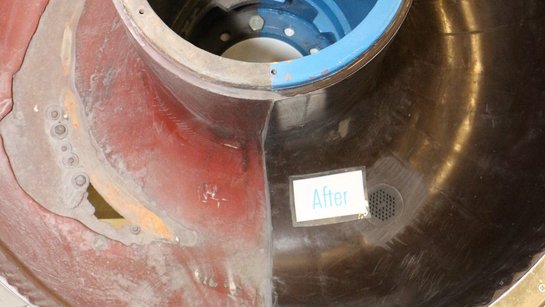
Adequate wear linings are an important factor in ensuring work pieces are efficiently handled in a mass finishing machine. Along with the method speed of transfer as well as the media selection and separation, the condition of a machine’s wear lining factors into the quality of process results. Thick linings assist with work piece handling by providing a cushioning effect, yet thin or damaged wear linings allow unwanted knicks, scratches, and dings. With more than 80 years of expertise in surface finishing, Rosler can assist with all aspects of your mass finishing process including proactively eliminating potential work piece handling issues. Observing Machine Conditions Regularly checking the lining of your work bowl(s) and trough(s) for wear is one way to ensure parts don’t get accidentally damaged during processing. Inspecting linings consistently will help identify repairable issues before permanent damage to the machine occurs. To effectively finish work pieces, media must be matched to the specific finishing task and the initial state of a work piece. For example, media used for deburring/edge radiusing and surface grinding can be very abrasive. If not properly protected by a suitable wear lining, the steel construction of a work bowl would be completely worn through in a few hours by contact with the media and work pieces. Polyurethane and, to a certain degree, rubber are excellent lining materials providing wear protection for thousands of operating hours. Even these materials wear through and must be periodically replaced with a new lining. Small areas can be temporarily patched with Polyurethane Repair Kits until the unit can be removed and professionally relined. If a reline is required, only use a qualified reline supplier such as the lining shop at Rosler. Relines are available in different degrees of hardness (shore A) and different qualities. Always make sure that the lining material is suitable for your specific mass finishing process. More information about specifying liner materials is available in a previous blog post . Side-by-side comparison of a vibratory bowl before and after relining Maintaining Process Stability Checking your work bowl lining for wear and replacing it in a timely manner is essential for the stability of your mass finishing process as a whole. In addition to worn work bowls, failure to ensure a proper protective lining can create other problems including: Work pieces getting stuck in the machine and, therefore, jeopardizing the integrity of different work piece batches. Media, water, and process chemicals can leak from the machine if the metal processing bowl is worn through and holes or cracks appear. Severe machine malfunction can occur when media or parts can get trapped in worn spots during the separation phase when the finished work pieces are separated from the media. Damage to the work bowl that is beyond repair, causing unnecessary downtime and requiring costly replacement parts. A weakened bowl can crack and make the entire machine unusable. Check your bowl lining at least monthly for wear or rips. The areas around drains, the parts loading chute, and around the unload areas will see the highest wear and are especially crucial. The “nail test” makes checking the liner thickness easy. Push a nail through the liner until you hit the base metal and record the thickness of the liner. Keep track of the liner thickness over time to predict when you will need to replace your liner. Most liners are between 5/8 and 1 in (15-25 mm) thick. Plan to get your machine relined when the thinnest part of your liner is less than 1/4 in (6 mm) thick. Just as optimal media mix must be regularly monitored, so must the condition of a work bowl. If not, the entire process and downstream operations may suffer. The Rosler Way Maintaining adequate wear linings protects your work pieces, equipment, and overall mass finishing process. Contact us for mass finishing expertise and insight. The complete Mass Finishing Work Piece Series includes: Part 1 – Selecting the Best Work Piece/Media Separation Method . Part 2 – Preventing Drop Height Damage . Part 3 – Maintaining Wear Linings .
emi-automatic centrifuge Z 800

Rösler Smart Solutions: Digital management of the process water parameters – Better process understanding improves mass finishing results

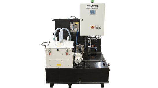
In his very first diesel engine Rudolf Diesel used already springs from the Siegmund Scherdel wire drawing company founded in 1889. Since then the company has evolved into a globally active operation that deals with forming, assembly and joining technologies as well as surface treatment. In addition, the company is also active in the manufacture of tooling and equipment. With 32 facilities around the world Scherdel actively supports its customers with services that range from initial briefings to volume production. The result are premium products that are not only used in the automotive industry but also in medical and electrical engineering as well as power generation. The products include stamped and bent parts, lock washers and components for electric vehicles. The latter are produced at the Scherdel Waldershof GmbH & Co. KG in Waldershof, Bavaria. The components made from different steel alloys, stainless steel and non-ferrous metals frequently receive their final surface finish in mass finishing operations. Besides the basic finishing tasks like deburring and edge radiusing, clean surfaces with a high degree of cleanliness are an important requirement. Clean surfaces are essential for conducting a proper optical quality control. In this context the quality of the process water plays a key role. Process water cleaning and recycling – for complex mass finishing applications At Scherdel Waldershof the process water from the mass finishing operation is cleaned and recycled with a semi-automatic centrifuge. However, to date the process water quality was only controlled by a daily check of the compound concentration. And this was usually done by different people who had little understanding and knowledge of the intricacies of the process water cleaning and recycling operation. „The process water gets contaminated by oil from the stamped & bent parts, belt lubricants and metal and media fines. On the one hand this increases the conductivity, which can cause faulty readings during the optical controls. On the other hand, the guidelines regarding particle size and quantities were not always followed. All this resulted in costly rework and even scrap parts“, explains Tobias König, department manager for mass finishing & cleaning at Scherdel Waldershof. Digital process water management results in transparency and generates knowhow When Rösler suggested to him to test the digital process water management system “Advanced” from Rösler Smart Solutions as a pilot user, the department manager immediately agreed. This new software package for semi-automatic and fully automatic centrifuges allows the user-friendly monitoring, recording and evaluation of all essential process parameters. These are: The compound concentration (measured by titration or refraction index – BRIX), pH value, conductivity, water hardness, microbiological contamination by bacteria, yeast and fungi, chloride content, COD value (chemical oxygen demand), BIT content (biocides in the process water), appearance and smell. Depending on the particular requirements for a given mass finishing process, the respective process parameters can be individually selected. In the “Advanced” version of the digital system the water samples are manually collected and analyzed with suitable measuring equipment that can be supplied by Rösler with the software package. The determined values are also entered manually. Based on the entered data the algorithm in the software develops recommendations for immediate corrective actions so that deviations from the specified values for the respective process parameters can be corrected and, thus, ensure process stability. Besides the recommendations for immediate corrective action the software also provides information that explains the adverse effects on the work piece surface, if the various parameter deviations are not quickly corrected. Since all data are recorded, they can be retrieved and displayed in the form of tables and time charts. This helps prevent costly downtimes by unplanned process water changes and allows to schedule such changes for time periods when they are less disruptive. „When Rösler presented the digital process water management system, we immediately recognized its potential for more transparency and a higher process stability. In addition, we realized that the recommended corrective actions along with the respective background information can be a tremendous educational tool that helps to increase the process knowledge of our employees“, concludes Tobias König. Increased process stability and improved finishing quality Scherdel Waldershof uses the digital process water management system with a semi-automatic Rösler centrifuge, model Z 800. This centrifuge cleans and recycles the process water from a Rösler mass finishing vibrator (model R 620) running in 3 shifts. The system controls the compound concentration and the pH value once per shift. A conductivity measurement takes place once per week. The microbiological contamination is checked whenever required. For example, this is the case, when the regularly monitored appearance and smell of the process water indicate that there might be a problem. The department manager explains: „The measurement and recording of the parameter values is easy and simple. We need about the same time for measuring and recording the compound concentration and the pH value as before.” He continues: „However, today we automatically receive an easy-to-read evaluation and a list of corrective actions that can be immediately implemented. This is a valuable tool to keep the process water stable and maintain a consistently high part quality. We have seen a reduction of rework and scrap parts by up to 50 %.“ The digital system issues not only recommendations for corrective actions when the parameters deviate from their rated values. Similar actions are proposed in case of events affecting the part quality and downstream manufacturing operations like corrosion, excessive foaming during the mass finishing process and insufficient cleanliness of the work pieces. To eliminate such problems the digital system issues detailed background explanations along with the recommended corrective actions. Tobias König concludes: „Most of the employees in my department have no special knowledge regarding mass finishing and handling of the process water. However, with the recommended corrective actions they not only learn what needs to be done, but they also acquire valuable process knowledge. This helps them understanding the relationship between the process water quality and the quality of the finished work pieces.“

Testing & Expertise Overcome Shot Blasting Challenges

For nearly a decade, Sales Representative and Interim Product Manager of Turbine Blast Equipment Zack Murray has been one of Rosler’s top shot blasting experts. Working with customers and our global Customer Experience Centers , he helps develop and test surface finishing machines and media in addition to dialing in specific process parameters. At times, adhering to the Rosler motto and guiding principle of “finding a better way
” can be difficult and complicated. Luckily, Murray and the entire Rosler team are committed to delivering world-class surface finishing equipment, consumables, and service in a variety of industries . In this post, Murray shares the most challenging issue he has tackled at Rosler and how the team developed a solution. The Problem A customer contacted Rosler for help in processing relatively large magnesium automotive parts. Considering the need for high throughput speeds in combination with the size of the parts, Murray knew a turbine blast machine would be the best option. Shot blasting turbine “In turn, the indication of a turbine blast machine meant that we were limited to metallic blast media,” Murray said, “as these machines are not typically suitable for mineral-based blast media such as aluminum oxide or glass beads. “Magnesium is a tricky material to blast in a turbine machine since it is prone to sparking with most metallic media. In addition to the fact that magnesium dust is highly flammable and combustible, we needed to avoid a potential recipe for disaster.” The process had to safely and efficiently deliver deburring and edge radiusing while minimizing the potential for sparking. The Solution Understanding that a relatively soft metallic media was required for safety and effectiveness, the team was left with the choice of aluminum or zinc blast media. Testing both media types demonstrated that results from the aluminum media most closely aligned with the customer’s desired process results. “Unfortunately, aluminum dust is also highly flammable and combustible,” Murray said. “The combination of the magnesium and aluminum dust was potentially dangerous enough to warrant an St3 Dust Hazard rating, which is the most severe rating, indicating a very high potential for fire and/or explosion. “Since the customer was not at a point in their product development cycle where they could get a dust hazard analysis performed as a result of part availability, we had to assume that the dust would be rated at St3.” As such, a wet dust collector with an anti-oxidizing compound dosing system was suggested for the customer with the further recommendation that the dust collector be installed outside, away from areas that commonly see human traffic, and that exhaust air was absolutely not allowed to feed back into the building. Rosler RF 550 NS including sludge drag conveyor and high-efficiency design to reduce residual dust The Rosler Way With more than 80 years of experience and a portfolio containing more than 15,000 equipment and consumable products, solving challenges is what we do at Rosler. Testing for safety and efficiency is an important step in achieving a stable and repeatable surface finishing process. Contact us today to request free test trials in one of our global Customer Experience Centers and allow us to develop a solution for your unique challenges!

Blade Technology: Straight vs. Curved Blades Explained

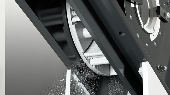
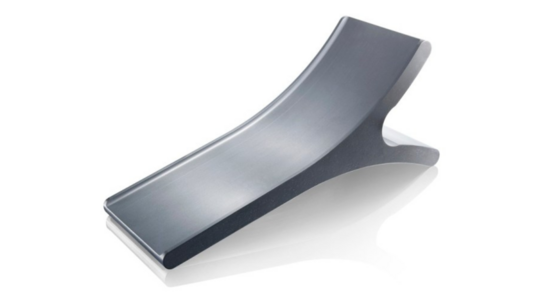
As an expert in the shot blasting industry, Rosler knows about blade technology. All shot blasting machines require blades to propel media towards workpieces. While both straight and curved blades are used, each type offers advantages and disadvantages. What are the Differences? Straight blades are, as the name suggests, blades that do not have curvature when viewed from the side and do not possess tangential curvature with respect to the turbine. Curved blades are blades that have some degree of curvature when viewed from the side. As the newer design, curved blades are generally better than straight blades, but they also have some drawbacks related to longevity, maintenance, and cost of ownership. Wear Rates Historically, the largest disadvantage of the curved blade design is that the blade will wear at a disproportionate rate along the length of the curvature, meaning that the curved blade design would wear through quicker than straight blade design. Modern technology has allowed the industry to overcome this particular flaw through the careful selection of curvature angle of the blade based on blade material properties to the point that curved blades now have similar usable lives to straight blades. Change Out Times A further disadvantage that has historically plagued the curved blade design is that the shape of the blades and fixturing take longer to change out than straight blades. The Rosler Gamma G turbine with forged metal blades overcomes this issue through the use of a retaining pin allowing for rapid blade change outs . This problem still currently persists for hard metal blade designs. Cost The final disadvantage is that curved blades tend to be more expensive than the straight blade designs, depending on the blade material. For cast and forged blades, the price difference is relatively small; however, for hard metal machined blades, the cost difference can be quite significant. Advantages Despite the disadvantages, curved blades also offer advantages over traditional straight blades. The largest advantage that the curved blades offer over straight blades of equivalent size is that the curved blades have a greater radial component to their velocities while maintaining an equivalent tangential component. This provides a higher throwing speed of the blades on the media (at equivalent turbine rotational velocities and equivalent turbine diameter) and therefore greater impact energy being transferred to the workpiece, allowing for the removal of more severe contaminants. Alternatively, if greater impact energy is not needed, the turbine’s rotational velocity can be controlled via a variable frequency drive to slow the turbine down which, in turn, provides a greater media throughput at equivalent media throwing speeds when compared against a straight blade turbine. Curved blade designs function at their best when the parts have very difficult finishing requirements or when greater part throughput is necessary. Orientations Curved blades have two types of orientation that can be used: a γ (The Greek letter gamma) shape and a C shape. The C shape has a greater curvature angle, allowing for a greater velocity/energy efficiency; however, the γ shape blade has a blade longevity factor in that once one side has been worn down, the blade can be flipped for a second use, effectively doubling the blade’s life. This is also an advantage over most straight blade designs. C-shaped blade Furthermore, the C shape does not have the ability to utilize a retaining pin for rapid blade changeout . The curvature angle of the blade (and therefore the blade's velocity and energy gain in comparison to a straight blade design) provides an equivalent lifetime based off of the material properties of the blade, namely its metal hardness. For modern metals, a cast blade can support a nearly negligible curvature without severely impacting its life, while a forged blade is capable of supporting a curvature angle that provides approximately a 7% increase in velocity (approximately 15% increase in energy) and a hard metal machined blade supports a curvature giving up to approximately 15% increase in velocity (approximately a 32% increase in energy) (utilizing a C shaped blade for maximum gain). The Rosler Way You can count on Rosler to help you find a better way when it comes to blade technology. Contact us today to discuss your unique challenges so we can identify the right blade for your needs.
Handshake

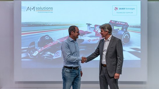
Sauber Technologies continues pursuing technological innovation as it extends partnership with AM Solutions, a brand of the Rösler Group

Sauber Technologies has extended its technology partnership with AM Solutions – 3D post processing technology, a brand of the Rösler Group, taking a further step forward in the field of technological innovation. The partnership, which was sealed in 2021, has been prolonged for two additional years, as a logical consequence of a valuable and trustful business relationship that has been providing both parties with excellent results. Automated post processing of additive manufactured parts is essential for Sauber Technologies for the economical production of repeatable and high-quality printed parts, especially on an industrial scale. Over the last year, the company benefited from Rösler's decades of experience in surface finishing, by using post processing equipment provided by its brand, AM Solutions – 3D post processing technology. Several 3D printed parts have also been featured on the Alfa Romeo F1 Team ORLEN C42, bringing the strategic partnership from the factory to the track. Under AM Solutions – 3D post processing technology, the Rösler Group bundles all activities related to additive manufacturing with an outstanding range of products and services, including systems, consumables and process engineering for the series-ready and automated post processing of additively manufactured parts. Rösler's many years of cross industry experience in surface finishing in a real production environment as well as its own mechanical engineering form a strong backbone of AM Solutions offerings. As part of the relationship between Sauber Technologies and AM Solutions, the two partners are currently collaborating in the field of SLA (stereolithography) in post processing, to develop solutions to maximise the efficiency of the cleaning process and support removal, a further milestone in surface technology. In addition, Sauber Technologies is already using several mass finishing and shot blasting machines from AM Solutions. Christoph Hansen, COO Sauber Technologies: “Over the past year, the partnership with AM Solutions has been of fundamental importance, as several business practices of our Group have been employing them, from the wind tunnel models to the most experimental components, and, of course, our Formula One cars. AM Solutions have brought their excellent experience and solutions to Sauber Technologies, helping us creating 3D printed parts faster and in a more efficient way, two essential qualities for an ever-evolving business like ours. I am glad to be extending our partnership with the Rösler Group, and I am already looking forward to seeing what else we could achieve together in the future.” Volker Löhnert, Managing Director of Rösler OberflĂ€chentechnik GmbH: "The extension of our partnership with Sauber Technologies is an important milestone for AM Solutions – 3D post processing technology. The team has a long tradition of using additively manufactured components in its Formula One cars and has been therefore interested in exploring the vast opportunities that 3D printing offers in terms of design, material selection, and lightweight construction. High-quality and repeatable post processing is of great importance for the optimization of the entire process chain, and that is where we bring our decades of expertise in surface finishing, together with our customized solutions developed specifically for the peculiarities of AM-manufactured parts. For these reasons, we have the perfect partner at our side in Sauber Technologies."
centrifugal disk finishing machine

Husqvarna relies on intelligently linked Rösler equipment

In its chain link production Husqvarna is utilizing three Rösler FKS 35.1 A2-So centrifugal disk finishing machines along with a fully automatic Z1000 process water cleaning centrifuge. For over 10 years these machines have reliably handled highly demanding finishing processes in a 24/7 manufacturing environment. Because of this outstanding track record and the excellent cooperation Husqvarna called on Rösler to provide technical assistance with a capacity expansion project. The company installed an additional centrifugal disk finishing machine with convincing new technical features and a second automatic centrifuge equipped with the software package “digital process water management” developed by Rösler’s Smart Solutions team. The seamless integration and intelligent linking of the new with the already existing equipment made the production of chain links more flexible and more cost-efficient. Above all, it resulted in a higher overall stability of the finishing operation. Elimination of capacity bottlenecks in the surface finishing operation Prior to the expansion and modernization project the centrifugal disk finishing machines were assigned to specific mass finishing processes. The strict assignment was intended to prevent the mixing of different process liquids and, thus, facilitate the process water cleaning operation. However, this rigid organization of the centrifugal disk finishing machines did not allow their flexible use. For this reason, the available finishing capacity could not be utilized in a cost-efficient manner and caused frequent manufacturing bottlenecks. To provide more flexibility, the new centrifugal disk finishing machine is equipped with a dual dosing unit allowing the machine to be connected to two process water recycling systems. This allows running different finishing processes in the same machine. In combination with the new process water cleaning centrifuge and the resulting increased cleaning capacity the finishing machines can now be flexibly assigned to the actual processing jobs without affecting the overall surface finishing quality of the chain links. Innovative technical features increase the process stability and reduce the cycle times The new centrifugal disk finishing machine is equipped with a custom-engineered work piece loading system. In addition, the special design of the processing bowl offers a higher working volume. But that is not all: Special flow guide segments along with anti-slip bars, a special spinner design and an increased drive power ensure a much better mixing of the work piece batches weighing several hundred kilograms. All this brought about a higher finishing intensity with shorter cycle times, increased the overall productivity and produced more consistent finishing results. Husqvarna was also impressed by the fully automatic adjustment of the gap between spinner and processing bowl. Manual gap adjustment and time-consuming gap measurements could be completely eliminated. The “intelligent” control system is automatically setting the gap to a size that matches the work pieces to be processed. Moreover, the control system continuously monitors the gap size during the entire finishing process and automatically adjusts the gap as needed. Rösler is the only company that offers such an advanced gap control system! Of course, with this sophisticated technology even very thin work pieces cannot get stuck in the gap. This prevents premature wear and potential machine crashes. Besides a much higher process stability the automatic gap control also increases the equipment availability by eliminating the time required for manual gap adjustment. Complete process control and traceability The purchase order from Husqvarna also included the linking of the mass finishing machines with a subsequent manufacturing operation. It covered not only the transfer of processing programs and process data but also the integration of the finishing machines into the existing Manufacturing Executive System (MES) at Husqvarna. This ensures not only a complete process control but also the monitoring of the equipment status and the finishing parameters. Digital process water management – up to 50 % lower water usage and longer uptime of the process liquid The process water cleaning process at Husqvarna is quite demanding. Therefore, the company was pleased to integrate the digital process water management system from Rösler Smart Solutions into its modernized process water cleaning and recycling operation. This innovative, interactive monitoring system for semi- and fully automatic centrifuges allows the monitoring, collection and evaluation of all essential process parameters. Suitable problem-solving recommendations are automatically issued. This helps to significantly reduce the water consumption and increase the uptime of the process water resulting in considerable cost savings. Based on a preliminary analysis the time periods between process water changes could be extended by 50 %. The resulting increase of the process water uptime also amounts to about 50 %. On-time completion of this challenging project The capacity expansion and modernization project could be implemented within a tight and quite challenging time frame. Despite the current supply chain difficulties Rösler not only met the agreed upon delivery date but could commission the equipment at Husqvarna two weeks earlier. Rösler Smart Solutions – Improved surface finishes and lower reject The Rösler Smart Solutions system is also used at the Scherdel Waldershof GmbH & Co. KG. This company produces stamped and bent components as well as parts for the automotive industry from steel alloys, stainless steel and non-ferrous metals. The mass finishing operation requires not only excellent deburring and edge radiusing results, but the work pieces must also be perfectly clean for the subsequent optical quality control. The process water is cleaned with a semi-automatic centrifuge. In the past the somewhat limited quality control procedure for the process water checked only a few parameters resulting in unwanted media and metal residues on the finished work pieces. This required costly rework, before the components could be delivered to the customers. With the digital process water management from Rösler Smart Solutions the situation could be completely turned around. The well-organized data output and the easy-to-understand action points from the “digital guide” ensure that the process water remains stable at a high quality. In turn, this produces absolutely clean work pieces. With the digital process water management system the rework and scrap rate could be cut in half. Digital process water management improves process stability and increases cost-efficiency At the Wegmann Automotive GmbH, global leader in the field of balancing weights, the process water from the mass finishing operation is cleaned in a fully automatic centrifuge. In principle, the operator manages the water cleaning and recycling operation quite well. Nevertheless, the company decided to install the digital process water management system from Rösler Smart Solutions. Because of different technical requirements the company recently had experienced some difficulties. Weights made from steel receive a corrosion protection in the mass finishing process, while zinc components must have a specified surface tension for a subsequent coating operation. These different requirements led to either a too high or too low compound concentration in the process water, resulting in considerable rework and large quantities of scrap parts. The customer had not considered the consequences of a microbiological contamination. In this case the interactive digital process water monitoring system from Rösler Smart Solutions produced a much more stable process and drastically reduced the rework and scrap rate.

How to Use a Vibrascope to Measure Vibratory Bowl Amplitude and Frequency

When it comes to mass finishing , amplitude and frequency require balance and careful consideration. Amplitude is a measure of movement and intensity while frequency refers to the rate of repetition. The wrong amplitude, for example, can create lackluster finishing results and longer processing times if it is too low. If too high, it can cause unnecessary wear and tear on the machine. Creating Vibratory Energy Whether rotary or tub style , mass finishing vibrators always include two key components: a work bowl containing the finishing media and the work pieces. Firmly attached to this work bowl is a vibratory drive system generating the energy to put the media and work pieces in motion. The work bowl with an attached vibratory drive system sits on a number of coil springs – in some cases on air cushions – which in turn sit on a machine base. The springs, respectively, act as air cushions allowing the work bowl to “free float” up and down within a certain distance. Example of vibratory drive The force from the vibratory drive system moves the media and work piece mix within the work bowl. Depending on the type of finishing machine, this force is generated by vibratory motors or electric motors driving a shaft with one or multiple imbalance units attached to it. Imbalance units are made up of a rotating shaft with out-of-balance counterweights at each end of the shaft. Due to its imbalance, the rotating shaft causes an intense wobbling effect. Common drive systems in vibratory bowls and tubs include foot motors for small tub vibrators, flange motors for rotary vibrators, and multiple imbalance units with electric drives for large tub vibrators. The Effects of Vibration Since the work bowl with attached vibratory drive system is loosely sitting on the coil springs or air cushions, the energy induced by the vibratory drive system causes the work bowl to move up and down within a relatively narrow distance band at the speed of the rotary drive system. The maximum up and down displacement of the vibrating work bowl from its position of rest is an indicator of the vibratory intensity and is called amplitude. Measuring & Reading Amplitude Understanding your machine’s amplitude is part of the process to dialing in precise surface finishing results. The amplitude – actually the double amplitude from upper to lower peak – is mostly measured in mm. In finishing vibrators, the amplitude is usually between 3 and 6mm. Rosler uses a visual devise called a vibrascope, a sticker applied to the outside wall of the work bowl, to visually measure amplitude. This sticker contains a row of 7 circles with diameters from 1 to 7 mm. Example of Rosler's Vibrascope sticker The simplest way of reading the amplitude is by observing the vibroscope sticker as the machine is in operation. The vibration of the work bowl has the visual effect of showing two rows of circles, with some circles being completely apart and some overlapping. The two circles which are apart but nearly touch each other represent the observed amplitude value. Adjusting Amplitude The vibratory intensity or amplitude of a machine is determined by three factors. Adjusting one or more of these factors will adjust the resulting amplitude. Speed of the Vibratory Drive System – Higher rotary speeds produce higher amplitude. Mass of the Imbalance Weights – Heavier imbalance weights produce higher amplitude. Angle or “Lead Angle” Between the Two Imbalance Weights – Smaller angles produce higher amplitude. The highest intensity is produced at zero degrees, while the lowest – practically no vibration – is produced at 180 degrees. Rosler advises adjusting one factor at a time for the most accurate fine tuning as well as safety and longevity of the machine. The speed and amplitude in finishing vibrators cannot be increased beyond a certain value; otherwise the machine would destroy itself. The acceleration, consisting of rotary speed and amplitude must not exceed 6g. At high rotary speeds, the imbalance weights must be set for a low amplitude (mass of the imbalance weights and lead angle). At lower speeds, the imbalance weights can be set for a higher amplitude. The Rosler Advantage Machines built by Rosler run with more frequency and less amplitude, meaning our media contacts a workpiece more times and is gentler than competing machines. This unique advantage of Rosler equipment creates less wear on media and machines while producing greater longevity. The ability to reduce amplitude yet deliver the desired surface finishing produces less machine shaking and part damage while slowing the rate of machine wear. When using vibratory bowls and tubs, most of Rosler’s competitors hit harder. While impressive, the force of those hits may not produce the most efficient results. Finding the Right Settings In the above graph, the numbers highlighted in yellow are the optimal combination of amplitude and frequency. Amplitude settings depend on the machine set-up, workpiece condition, and desired outcome. Not sure what amplitude is best for your unique needs? Trust the experts at Rosler to conduct a trial and dial in the results before you purchase a machine. The Rosler Way Whatever your mass finishing needs are, you can count on Rosler to help you find a better way. Contact us today to discuss your unique challenges and request a free trial in one of our Customer Experience Centers .

New Deflashing Equipment Assists 30-year Customer Increase Production

For over 30 years, Berker GmbH & Co KG (Berker) has trusted Rosler shot blasting equipment in its manufacturing processes. A member of the Hager Group since 2010, Berker is one of the leading manufacturers of high-end electrical components, from timeless classical switches to intelligent electrical systems for buildings. The company also supplies switches for electrical appliances and automobiles. The Situation Berker primarily uses continuous feed systems such as loop and flat belt machines to deflash plastic components including switching elements, electrical outlet covers, frames, and more. Increased production volume at its Wenden-Ottfingen manufacturing location led Berker to decide to invest in an additional shot blast machine in 2018. The new investment was intended to replace an existing continuous feed loop belt system with the latest deflashing technology. Its specifications called for increased capacity and high equipment availability. The Solution After the capacity requirements had been established, Rosler developed a system concept that fully met the customer’s technical and economic demands known as the RSBS 1702 continuous feed loop belt blast machine. Equipped with two direct-drive blast turbines , the new Rosler machine produces excellent deflashing results combined with an extremely high degree of process stability. The machine includes a host of technical features including modern PLC controls, an optimized media cleaning and recycling system with a vibratory screen and air wash separator, a sensor-controlled media replenishment unit, automatic replenishment and mixing of anti-static compounds, noise protection, an automatic standby module, and a dust collector. The new machine design also allows the automatic deflashing of large work pieces which could not be handled with the old equipment and has been in operation since 2020. The Advantages Rosler is grateful to have the opportunity to assist a 30-year customer achieve new efficiencies even in the midst of a global pandemic and labor shortage. Automated aspects of Berker's new system went beyond improved efficiency and capabilities to provide an additional advantage in the reduced need for manual labor. Like many employers, Berker has faced increasing competition for manpower. The use of work piece handling systems, conveyor belts, and robots have helped bridge the gap in human resources and maintain production rates. Additionally, in the world of manufacturing, this mitigation of human intervention offers even greater and more measurable efficiencies and consistent quality. The Rosler Way “Finding a better way
” is more than a motto at Rosler; it’s our mission. With more than 80 years of experience and a portfolio containing more than 15,000 equipment and consumable products , solving challenges is what we do. Contact us to learn how we can help you achieve more efficient, automated surface finishing.