Solution Finder
SOLUTION FINDER

Votre guide dans l'univers des produits l'univers des produits Rösler

En quelques clics, vous trouverez la machine qui répond à vos besoins !

Résultats: 237 Article - 52 Produits

New Compounds Double Process Water Usability

Experienced manufacturers know that optimum mass finishing process water handling, dosing, and recycling can significantly reduce operational costs and improve finishing results. With approximately 15,000 different products and the largest, continuously expanding range of media and compounds in the world, Rosler has the machines, consumables, and the experience to develop and maintain precise, efficient, and sustainable surface finishing processes. Our latest innovation in the field of consumables, Long Life Compounds known as LF compounds , allows mass finishing operations to further optimize their process water cycles. Advantages LF compounds utilize a special combination of raw materials to guarantee a remarkably high degree of sanitary stability. So much so that, in most cases, the addition of biocides to process water can be eliminated or greatly reduced when using these new compounds. Cleaner water, in turn, extends the usable life of your process water by nearly twofold. These savings in water and compound usage as well as associated disposal costs produce cost savings of up to 60%. These compounds also assist in optimizing mass finishing operations by lowering maintenance costs of the water recycling/circulation system itself and producing increased system availability and productivity. Applications Generally, any process with a recirculation system can utilize LF compounds. Finishing applications in need of increasing bactericides and hazardous substances, in particular, are good candidates for the use of LF compounds. Processes in need of defoaming compounds or additives also benefit from switching to LF compounds. Options Typically used to reduce issues of foaming, Rosler’s ZF compounds have been further optimized leading to the introduction of the long life LF compounds range. Effective properties of these existing compounds have been integrated into the new products along with improved system hygiene features. The LF compound line will continue to grow. Currently available formulas and their defining characteristics include: LF 110 – Offers the highest corrosion protection. LF 113 – Designed for universal application. LF 138 – Designed for universal application with good degreasing properties. The Rosler Way We understand that your work pieces deserve special treatment. When it comes to placing the optimal finish on their surface, you can rely on Rosler’s consumables and equipment. With more than 80 years of experience and an ever-evolving catalog of developments and innovations, we are confident that we can improve your surface finishing processes. Contact us to discuss your mass finishing and process water needs.
Mass finishing solutions for electric vehicles

Mass finishing solutions for electric vehicles

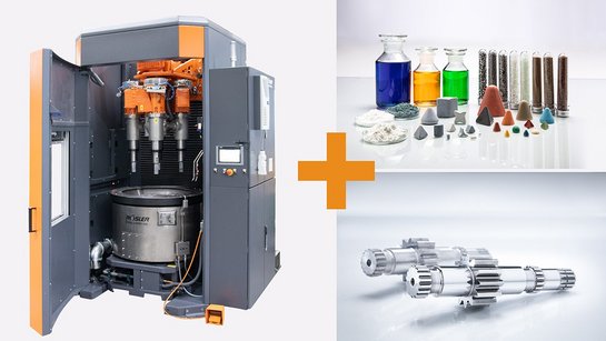
Vehicles driven by batteries or fuel cells and plug-ins contain a large amount of electrical and mechatronic components. These include connectors, circuit boards and busbars. For transferring the power they must handle high electric volumes. To function well, they must be free of burs and perfectly clean. For this surface finishing task the mass finishing technology represents a highly effective and economic solution. By fine-tuning the equipment and the consumables (media and compound), all developed and produced in-house, Rösler ensures that the required surface finishes are consistently achieved within short cycle times. Mass finishing systems are also used for finishing copper bars and various kinds of stampings. Copper bars are increasingly employed as winding material for rotors, whereas bent and stamped components are used for all kinds of housings. Friction causes not only increased wear and fuel consumption. It also generates unwanted noise emissions, vibrations and increased temperatures. Minimizing friction is, therefore, an important goal for components in vehicles that are powered by batteries or combustion engines. The optimal surface smoothing of components such as gears, cam segments, piston rings and camshafts are achieved with fully automatic mass finishing systems, for example, drag and surf finishers. The component surface is not only smoothed by removing roughness peaks and valleys. In addition, the components are also completely deburred. Such multi-function finishing operations in one single process generate significant cost savings and repeatable results.
Preservation line

Preservation lines in a class of their own

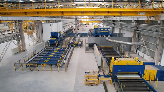
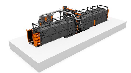
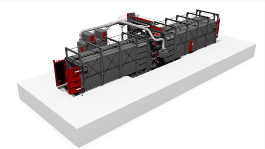
When it comes to top-of-the-line preservation lines, be it for shipyards or steel rolling mills, customers around the world rely on the technical competence of Rösler. This is not surprising, because Rösler offers not only comprehensive knowledge and many years of experience but has also implemented numerous reference projects. Another positive aspect are the project teams consisting of experts from the respective Rösler sales branches and the specialists from the head office in Untermerzbach, Germany. This close global cooperation produces technical solutions with numerous benefits to the customers. CMCS – successful entry into a new market segment China Merchants Cruise Shipbuilding (CMCS) is one of the leading manufacturers of expedition ships, floating platforms and floating cranes. To date the company had outsourced the corrosion protection of the steel plates and beams required for the production of its products. With the expansion of its business activities into passenger and cruise ships the company had to abandon this outsourcing policy. The construction of a midsize passenger ship alone requires 25,000 metric tons of steel. For this reason, the company looked for a partner for the design and installation of a high-performance preservation line . After an extensive analysis of the market the Chinese ship builder chose Rösler as supplier for this crucial investment. Key factors for this decision were the implementation and technical, efficiency of several preservation lines at European shipyards. Rösler was the only supplier who could present such an impressive reference list. Fully automatic interlinked steel preservation offers competitive advantages The 180 meter long preservation solution was specially engineered to meet the requirements of CMCS. It includes a plate section, the so-called main line, and a steel beam section, from which the shotblasted beams are fed into the main line. This unique preservation line consists of two roller conveyor shot blast machines, equipped with perfectly adapted Gamma 400G and Rutten 400 HD turbines , a straightening system for the beams and up to 12,000 mm long plates, a fully automatic coating system including a paint supply unit and a thermal post-combustion system. All these line components are digitally connected and integrated into the production control system of the shipyard. This intelligent control system allows the fully automatic processing of the steel components from the loading to the unloading zone at a speed of five meters per minute. The short pass-through times, a high process stability and consistent coating results provided CMCS with a significant competitive advantage. Of course, this was enhanced by the sturdy and wear-resistant design of the preservation line along with significantly lower personnel costs. A new dimension of corrosion protection for steel plates One of the largest manufacturers of steel and associated products with plants in the United States, Canada and Mexico convinced to purchase their new preservation line from Rösler. In this case it was the excellent experience with a preservation line installed a few years ago at another plant that prompted the major US company to choose a Rösler preservation line. The size of the steel plates with a width of 4,300 mm, a length of 18,000 mm and a thickness of up to 200 mm required a custom-engineered solution. Handling of loads of up to seven metric tons per running meter The entire line, in which the steel plates are preheated, shotblasted, painted and dried, had to be designed for loads of seven metric tons per running meter instead of the usual three tons. The integrated roller conveyor blast machine has a usable width of 4,500 mm and is equipped with 10 Gamma 400G turbines, each with an installed power of 30 kW. Such a “fire” power ensures that consistent, homogeneous shot blasting results are achieved across the entire width of the plates at a speed of 4 m/minute. This guarantees a high productivity.

AM Solutions Delivers Post-Processing Solutions for Prototypes & Parts

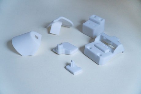
Knaus Tabbert AG is a leading manufacturer of recreational vehicles. The company’s innovative designs and powerful drive systems for motor homes, caravans, and panel trucks allow for safe, comfortable, and sustainable travel. At its German headquarters in Jandelsbrunn, Bavaria, Knaus Tabbert utilizes its comprehensive experience and know-how to continuously improve the materials and designs of its vehicles as well as new manufacturing technologies such as additive manufacturing. Seeking faster and less expensive post processing for its 3D printed prototypes, Knaus Tabbert turned to AM Solutions , a brand of The Rosler Group , to find a better way. Challenging Post-Processing From prototyping to production, Knaus Tabbert needed de-powdering and cleaning operations for additively manufactured work pieces. “On the one hand, we are using 3D printing technology for creating prototypes. On the other hand, we are also utilizing additive manufacturing for producing standard components in volume such as the bracket for an alarm system or the hinge mechanism for the swing-out shower stall,” said Mario Meszaros, Knaus Tabbert Development Engineer. De-powdering and cleaning of PA 12 polymer components produced by a powder-bed printing system were being done manually in a blast cabinet, producing highly erratic and inconsistent results as well as a lot of time and labor. The company wanted a more cost-effective and consistent automated alternative. Polymer parts used by Knaus Tabbert Comprehensive processing trials with different Knaus Tabbert components took place in the AM Solutions' Customer Experience Center . This division of The Rosler Group specializes in post-processing solutions for 3D printed components. After the conclusion of the highly successful processing trials, the customer chose the S1 shot blasting system . Perfect Cleaning & Quick Amortization The S1’s fully automatic operation delivers efficient finishing with absolute cleanliness. This shot blast machine was specifically developed for the post processing of plastic components produced with the powder-bed printing method. Featuring a plug-and-play design, the S1 is the only machine on the market to allow time-saving and cost-efficient de-powdering as well as surface smoothing and homogenization of 3D printed components in one single machine. All that is required is a simple change of the blast media , for example, from glass beads to plastic spheres. Equipped with a basket that rotates during the finishing operation and allows easy, ergonomic loading and unloading of the work pieces, the S1 offers fully automatic batch processing. Throughout the entire process—from loading and treatment to unloading—the basket remains in the machine housing. This, combined with a special door sealing system and antistatic system, prevents any powder spillage into the immediate surroundings. The control panel allows an easy and quick switch to manual operation without any retooling. “The fact that after surprisingly short cycle times the components came out of the machine perfectly clean and without any powder residues was very impressive,” Meszaros said. “With the underlying operating data, I prepared a ROI calculation. The results quickly convinced our management that, even with only three print jobs per week in the S1, we will achieve a return on our investment after roughly two years.” Since it is safe to assume that the quantity of 3D printed components will increase significantly, Meszaros said he expects that the amortization period will be drastically reduced as the S1 is used more extensively. Process Stability & Operational Safety In addition to excellent processing results and rapid amortization, the S1’s standard version also features a system that automatically monitors and records all relevant process parameters. The integrated blast media cleaning and recycling system drives high process stability by ensuring that media is always available in perfect condition no matter what type is utilized. The explosion-protected design of the shot blast machine with ATEX-compliant motors and valves provides additional peace of mind and safety. “I am absolutely convinced that the simple, effective, and efficient post-processing possibilities of the S1 will further promote the use of additive manufacturing in our company,” Meszaros said. David Soldan, Head of AM Solutions, agreed, adding that Rosler and AM Solutions provide finishing solutions to a variety of industries . “More and more companies from different industries are choosing the S1 for post processing their 3D printed components,” Soldan said. “This confirmation of our product strategy shows that our 3D post-processing products are in full compliance with the requirements of the market.” The Rosler Way “Finding a better way
” is more than a motto at Rosler; it’s our mission and why AM Solutions exists. With more than 80 years of experience and a portfolio containing more than 15,000 equipment and consumable products, solving challenges is what we do. Contact us today to discuss your additive manufacturing post-processing challenges!
RWK swing chamber blast machine

We are helping to build the car of the future

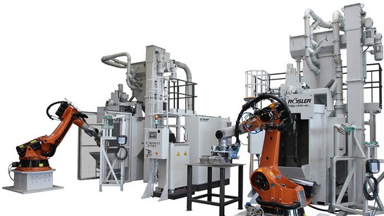
Integrable swing chamber blast machine enables parts processing in the production cycle The transformation of the automotive industry continues apace. At the beginning of June, the European Union decided to ban the sale of combustion engines from 2035. Subject to the approval of the individual EU member states, only electric cars or comparable climate-neutral vehicle systems may then be sold. To further increase their range, carmakers will rely even more on lightweight components in the future. However, lightweight components have already been used increasingly in automotive construction for years, for example to reduce emissions from classic internal combustion engines. Lightweight components include stator carriers, housings and components for drive technology, as well as axle and wheel mounts. These are produced by sand, pressure or injection molding. The parts then have to be finely desanded, deburred and their surfaces homogenized. For this purpose, our blasting technology experts at Rösler develop customized solutions. One of these is our compact swing chamber blast machine with automated parts handling. It was developed in such a way that it can be integrated into compact production lines in a space-saving manner. This enables parts processing in a production cycle - efficient, process-oriented and innovative. The advantages of the RWK swing chamber blast machine: Shortened cycle time due to simultaneous blasting as well as loading and unloading process Optimal for integration into existing production lines Process-safe pick-up of components due to integrated pneumatic clamping unit High blast intensity thanks to high-performance turbines Blast chamber made of manganese steel with additional exchangeable plates

Mass Finishing Work Piece Handling Series, Part 1 – Selecting the Best Work Piece/Media Separation Method

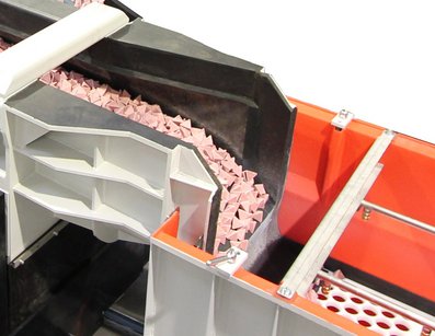
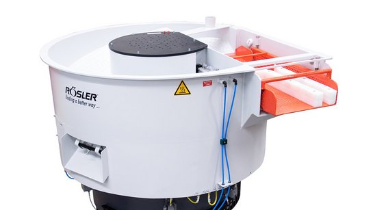
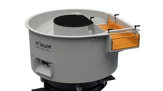
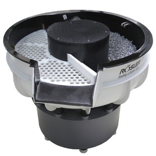
One of the first considerations in finishing process development is the ability to effectively separate mass finishing media from the work pieces. If separation cannot be achieved, the process will not be viable. Signs of inadequate separation may include the need for too much manual intervention, lodged media causing downstream process issues, failure to meet finishing standards, or even product recalls. For processes that do not require work pieces to be firmly mounted to fixtures in the machine, components and media loosely tumble in mass finishing processing bowls and troughs to achieve the desired finishing result. While this interaction is encouraged during processing, swift and precise media separation is crucial before work pieces move onto the next process step. Rosler has more than 80 years of experience designing mass finishing machines and supplying consumables. Our expertise can help develop the best separation method and settings for your unique combination of finishing, work pieces, and media. Separation Objectives If not properly removed from work pieces, media carried out of the machine can cause disastrous results in automated, downstream manufacturing operations such as machining, assembly, painting, etc. The manner in which media and work pieces are separated matters as well. The separation stage must not be too aggressive, as it could damage the finished work pieces with nicking and scratching if not carefully calibrated. Media and work pieces exit the machine outlet and pass over a polyethylene screen with round holes for external separation Separation must also take place in the shortest possible time to avoid costly extensions of the overall cycle time. The separation process should not require any support by the machine operator such as manually holding back the media/work piece mix on the separation screen. Separation Speeds While all machine types must meet the aforementioned separation objectives, some types require extra adjustments for vibratory motor speeds to aid the separation process within the machine. Where possible, separation is done in the finishing machine. This reduces the need for media handling, as the media remains in the machine and the parts are separated via built-in separation screens. Reducing the machine speed in rotary vibrators , long radius machines, and vibratory dryers after the higher intensity processing cycle provides more effective separation and minimizes part-on-part damage during the parts unloading step. Rosler rotary vibrator with internal separation screen Machines that require unloading the media/part mix from the machine at the end of the finishing process usually use external screening systems to separate the parts from the media. The external screening system has its own vibratory drive system that can be set and adjusted to maximize the screening speed while providing gentle part transportation. Rosler rotary vibrator with internal separation screen In either case, it is very important to select the correct screen type and hole size. Holes that are too small may cause media carry‐out while holes that are too large might cause work pieces to lodge in the screen or even fall back into the machine. The screen deck length must also be carefully considered. Methods of Separation In mass finishing, screen and magnetic methods of separation are most common. Separation Screens Available in a wide selection of hole sizes and shapes, separation screens are made of a variety of materials. Screen types include (top, from left) polyethylene screens with round or oblong holes, (middle) wire mesh screens coated with polyurethane or made from steel, and (bottom) bar screens made from steel or polyethylene Rosler offers numerous screen options, including: Polyethylene screens with round or oblong holes. Wire mesh screens coated with polyurethane or made from steel. Bar screens made from steel or polyethylene. Magnetic Separators When screen separation is difficult or even impossible, magnetic separators are a good alternative. For example, when the work pieces and the media have a similar shape or are the same size, magnetic separation is an excellent option. The use of magnetic separators requires that work pieces are ferrous and attracted by a magnet. These systems can be configured with a drum or belt as well as demagnetizing zones. Rosler magnetic drum separator Rosler magnetic belt separator Updates for Existing Systems Consult with your supplier to learn about the available separation options for the mass finishing machine you are using or intend to use. Available equipment updates may include: Frequency inverters enabling you to vary the motor’s speed. Most vibratory motors run at two speeds; namely 1,800 RPM (4‐pole mode) or 1,200 (6‐pole mode) by default. Installation of different screens utilizing different materials and hole sizes and shapes. Magnetic drum or belt separators. Regardless of the upgrade, ask your supplier to run a test processing trial before installation to ensure the change is satisfactory. Rosler offers free testing in our global Customer Experience Centers . The Rosler Way Decades of experience and ability to design, service, and maintain machines as well as the consumables and accessories to get the finish you require make Rosler a well-rounded surface finishing expert. Contact us to discuss your mass finishing and work piece handling needs. The complete Mass Finishing Work Piece Series includes: Part 1 – Selecting the Best Work Piece/Media Separation Method . Part 2 – Preventing Drop Height Damage . Part 3 – Maintaining Wear Linings .

Mass Finishing Machine Settings Series, Part 2 – Determine Imbalance Weight Settings for Consistent Results

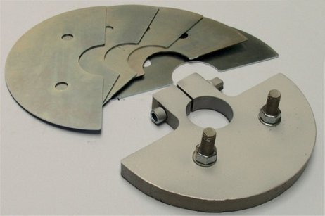
Specific mass finishing applications are developed through processing trials. Once defined, users should not deviate from the determined machine settings unless necessitated by work piece or process changes. Rosler partners with clients to provide testing in our global Customer Experience Centers to demonstrate our capabilities on a specific work piece and to calibrate machine settings. Determining the exact machine settings requires considering and testing multiple factors. Vibratory Systems The most common drive systems in mass finishing are vibratory. This refers to actual finishing machines such as rotary , tub , and linear continuous flow vibrators as well as auxiliary equipment like screening systems, vibratory conveyors, buffers, etc. In all of these cases, the speed of the vibratory motor or the electric motor driving the imbalance unit(s) may have to be adjusted as well as the setting of the imbalance weights. Vibratory weight plates The angle between the upper and lower imbalance weights determines the movement of the media and work piece mix within the machine. The number (mass) of imbalance weights determines the processing intensity (amplitude). More weights produce higher intensity while fewer weights deliver lower intensity. Vibratory motor diagram Setting Imbalance Weight s The movement of the media/work piece mix is always opposite to the motor direction. Typically, the motor runs clockwise and the media/work piece mix runs counter clockwise. In some instances, the motor can run clockwise and counterclockwise including the Rosler “R” machines and gate clearing in Rosler “Euro” machines. Half-circle metal plate weights on the top and bottom of the motor must be positioned with respect to each other. For a basic setting, the bottom weight plate must be turned 90 degrees forward of the top weight plate, in a basic setting. Imbalance weights locations and settings within a vibratory motor When setting imbalance weights, it is important to understand the impact of changes. For example, increasing the lead angle will make the media/work piece mix travel around the work bowl faster. Decreasing the lead angle will have the opposite effect, slowing movement. Typical lead angles range from 70 to 120° and can be observed by checking the gauge on the top of the motor shaft. Vibratory motor lead angle gauge Within the imbalance weights, the top weight controls the travel speed of the media/work piece mix around the work bowl. Adding additional weights to the top will increase the travel speed while decreasing the spiral speed in the work bowl. The top imbalance weight controls media and workpiece speed around the work bowl as represented by the red arrow while the bottom imbalance weight controls the spiraling speed of the work bowl contents. The bottom weight controls the spiral speed of the media/work piece mix in the work bowl. Conversely to the top weight, adding additional weights to the bottom will increase the spiral speed but also decrease the travel speed around the work bowl. Action Points Regularly checking a mass finishing machine’s settings including motor speed(s), setting of imbalance weights, work station angles, etc. to ensure they are as initially established will produce better results and protect the systems ROI. A vibrocope sticker on the work bowl allows for a quick check of the processing intensity. Additional information can be found in our Using Vibrascope to Measure Amplitude v. Frequency in Vibratory Bowls blog post. Virboscope sticker Additionally, if repairs require drive motors to be disconnected, make sure that they are rewired correctly and are not running in the wrong direction. If the machine settings must be changed, carefully follow the instructions in your operator’s manual or consult the manufacturer for assistance. If not already integrated, installation of a frequency inverter for precise setting of the drive speed of your machine may be available as an upgrade, providing additional control and oversight. The Rosler Way Rosler goes beyond developing mass finishing machines to provide operational insight and guidance for the lifetime of our machines as well as consumables and service . Contact us to discuss your needs and our capabilities. The Mass Finishing Machine Settings Series also includes Part 1 – Improve Machine Function with Proactive and Responsive Observation, Calibration .

Customer Experience Centers Offer Free Surface Finishing Insight & Solutions

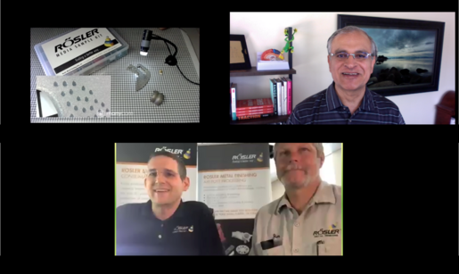
During more than 80 years in business, the Rosler team has gained extensive experience in shot blasting and mass finishing for a variety of industries . In addition to the machinery and consumables we provide, our Customer Experience Centers enable us to demonstrate Rosler’s expertise by processing your samples with settings and requirements tailored to your needs. Sending your work pieces to one of our 11 test centers around the world is an important step in achieving the perfect surface finishing process. Learn what to expect from Rosler’s Customer Experience Centers and get the most out of your partnership with Rosler from Sales Representative and Interim Product Manager of Turbine Blast Equipment Zack Murray and Mass Finishing Product Manager Michael Salyers. What to Expect as a Customer To achieve optimal processing results, we carry out sample processing step-by-step. With an emphasis on finding a better way, our process includes: A joint kick-off meeting (in-person or virtually) between your team and Rosler experts to set the processing objective. Determination of the process technology. Sample processing. Appraisal by Rosler shot blasting or mass finishing experts. In some cases, both. Creation of detailed test and measurement reports. An opportunity for you to evaluate the results and a final meeting. Salyers, a mass finishing expert with four years of experience at Rosler, describes the sampling process as collaborative and informative. “The customer gets the chance to meet all of the key players involved in the project. They have the opportunity to ask any questions they may have, review the equipment available, and discuss the pros and cons of each,” he said. “As a team, we review the customer’s parts, goals, and expectations. Based on many years of experience, our team will consider each factor involved with finishing the part, select the most appropriate machine, media, and compound, and then run test trials in order to reach the stated goal.” Whether you are in search of a mass finishing or shot blasting system, you can expect a team who will listen to your desires, uncover and discuss your pain points, and then develop a solution that best fits your goals, Salyers said. Murray, a shot blasting expert with nearly nine years of experience, agreed but said the shot blasting sampling process typically starts with more options already predetermined. “A large majority of the time, customers already know what shot blasting media they are going to be using—either because they are already using it in a different machine, a sisterplant of theirs is using it for similar applications, or an upstream application is currently outsourced using that media,” he said, “Therefore, the only things that need to be verified are time cycles for batch or single part processing applications or throughput speeds for continuous throughput applications.” Rosler CEO Bernhard Kerschbaum (bottom left) and Customer Experience Center Process Expert Jim Kellay (bottom right) meet virtually with a customer to discuss a test batch and demonstrate Rosler’s capabilities without the need for an in-person meeting. The typical testing experience does not even necessitate the customer’s presence on-site, Murray said. Testing can be accomplished by the customer sending sample work pieces to Rosler which are then processed with different cycle times or throughput speeds and sent back to the customer for evaluation. “For the relatively rare case wherein the customer is in need of our support for media selection and th eprocess needs are special enough that we don’t have an ‘off-the-shelf’ solution ready based on previous experience, Rosler tries to have the customer visit our facility for the testing,” Murray said. “We do an initial round of testing in our manual air blast or wet blast cabinets using a small cut of the part for larger parts or a small batch of the parts for smaller parts so that we can quickly change out the media to show the results of several materials and/or sizes of media. Once the customer has verified which media gives them the finish they are looking for, we do a separate test to verify time cycles orthroughput speeds.” Preparing for Testing While testing in our Customer Experience Centers is free of charge to prospective and current customers, Rosler understands that your time is valuable. Gathering the right information prior to testing can help expedite your test trials and enable us to develop the exact system for your needs more quickly so you can implement changes or plan for system upgrade investments sooner rather than later. Gathering information for testing typically begins with a one-page initial inquiry questionnaire specific to mass finishing or shot blasting. Both versions contain questions related to processing objectives, final surface quality, work piece conditions and specifications, desired processing modes, reason for investment, project budget, and desired timeline. Specific to the type of surface finishing sought, each questionnaire also addresses current systems in use and more process-specific information. Rosler Customer Experience Center Process Expert Jim Kellay conducts a virtual test trial review with a customer. “Our goal is to create a collaborative process,” Salyers said. “The more information a customer can provide regarding their problems and goals, the more effective solution we can develop. “No two projects are the same. There is no magic bullet or media for every part. Each part must be considered individually before a comprehensive process can be developed.” Rosler’s ability to communicate the potential and limitations of shot blasting and mass finishing for specific customer processes relies on understanding the customer’s initial work piece condition and end goal, all finishing steps utilized, and productivity metrics sought. “Communication is the key in identifying unrealistic expectations as well as identifying innovative solutions,” Salyers said. “Fully understanding the customer’s needs and goals in the beginning helps us achieve maximum results for them.” Visual inspection of knee femorals after tested processing in Rosler’s United States-based Customer Experience Center for the desired surface finish. The Rosler Way “Finding a better way
” is more than a motto at Rosler; it’s our mission. With more than 80 years of experience and a portfolio containing more than 15,000 equipment and consumable products, solving challenges is what we do. Contact us today to get our Customer Experience Center to work developing a solution for your surface finishing challenges!
Dutch Equipment Manufacturer Increases Flexibility with Automatic Shot Blasting

Blast cleaning is uniquely capable and efficient at delivering the pre-coating surface preparation required for components that must be able to withstand severe ambient conditions including heavy equipment for construction and mining, agricultural machinery, transportation and material handling equipment, and railway equipment and rolling stock. When Dutch equipment manufacturer Delwi Groenink sought a better solution for prepping its various steel weldments for painting, the company enlarged its manufacturing depth with a new continuous hanger shot blast machine from Rosler . The Situation Based in Enschede, Netherlands, the company designs and produces numerous products including placement systems for container pads. Its customers largely work within the material handling, offshore, and transportation sectors. Prior to the new system, pre-treatment of steel components utilized various external job shops for manual shot blasting in labor-intensive blast rooms and paint booths. In addition to complex logistics, the process was also time-consuming. The Solution To accelerate the manufacturing process and become more flexible, the company decided to bring these processes in-house and took over the job shops including their staff. To further optimize operations, Delwi Groenink invested in a modern shot blasting machine , which was placed in a new building adjacent to the painting facility. The company selected Rosler’s continuous hanger shot blast machine RHBD 27/32-K after shot blasting trials with Delwi Groenink components in our Customer Experience Center in addition to demonstration of similar Rosler systems in the field, and Rosler’s technical service in the Benelux countries. The Specifications The RHBD-K is designed for continuous processing of single components and batches of multiple work pieces with dimensions up to 10 ft (3 m) long, 10 ft (3 m) wide, and 40 ft (12 m) long. The blast chamber is manufactured from manganese steel. Easy-to-exchange, gap-free manganese liners are also added in areas exposed to the blast stream for added protection. The required high blasting intensity is generated by 16 Gamma 400 G turbines , each with an installed power of 11 kW. The turbines are arranged vertically in two rows on the left and right wall of the blast chamber, with the two rows being somewhat offset from each other. Combined, the turbines throw approximately 5,000 lb (2,240 kg) of blast media per minute. This ensures excellent blast coverage and uniform preparation of all surfaces. The special “Y” design of the throwing blades and the optimized media transfer in these Rosler high-performance turbines allow a highly fluidized media movement with little or no turbulence. Compared to conventional turbines of similar sizes, the resulting higher throwing and impact speeds produce a 15- to 20-percent-higher blast performance. Blasting efficiency is further improved by the concentrated blast pattern. Moreover, both sides of the throwing blades can be utilized resulting in a doubling of the uptime of the throwing blades. All these technical features, along with the fact that the blades can be exchanged within only seven minutes, convinced the customer. The Process Once a steel weldment has been transferred to the transport truss, the RHBD-K recognizes that a component is ready to be blasted and transports it into the entry chamber. As soon as a sensor monitoring the front area of the blast machine signals that no people are present, the double-leaf door closes automatically. According to the part-specific treatment program, all or some turbines then start up and blasting begins in the blast chamber. This blasting intensity can be adjusted with frequency inverters. After completion of the blast cycle, the work piece is transported into the exit chamber, media flow is interrupted with shell valves, and turbines turn off allowing the operator to manually remove blast media and dust from the work piece. Once finished, the operator leaves the exit chamber and signals another sensor to initiate and open the double-leaf doors so a transport truss can remove the work piece from the machine. Designed to handle a media throughput of around 2.5 metric tons per minute, the media recycling and cleaning system includes an elevator, cross auger, and air wash separator. The Rosler Way “Finding a better way
” is more than a motto at Rosler; it’s our mission. With more than 80 years of experience and a portfolio containing more than 15,000 equipment and consumable products, solving challenges is what we do. Contact us today to discuss your surface finishing goals and how we can deliver improvements!

Mass Finishing Machine Settings Series, Part 1 – Improve Machine Function with Proactive and Responsive Observation, Calibration

Even if the finishing media and compound/water are managed perfectly, without a well-functioning machine a mass finishing process is doomed to fail. Focusing on a few essentials will ensure that a mass finishing machine is performing as intended. From machine settings to preventative maintenance and troubleshooting tips, Rosler has the experience and insight to keep mass finishing machines running efficiently. The Right Machine Settings The speed at which a machine is running is critical to the success of a finishing process. If the machine is running too slow, the finishing results, deburring/edge radiusing , surface grinding , etc., might not be achieved at all or only after excessively long processing times. If the machine is running too fast, the work pieces may be damaged by scratching, nicking, or bending. Excessive speeds will also cause the media to wear much faster without the benefit of shorter cycle times. Beyond speed, other machine settings must be taken into consideration based on the specific machine type. Rosler's R 420 EC vibratory tub machine with media Vibratory The energy required to move the media and part mix in a rotary , tub , or linear continuous flow vibrator is created by the vibratory motor and imbalance weights. As such, the motor speed, setting of imbalance weights, and the mass of imbalance weights are adjusted to match the processing needs. Rosler's FKS centrifugal disc machine from above Centrifugal Disc Finishing Rotation of the spinner in the bottom of the processing bowl produces energy needed to accelerate the media and parts batch in a centrifugal disc finishing machine . The speed of the drive motor and the ribs on the spinner should be regularly evaluated to ensure effective energy transfer. Rosler's R6/1000 with automatic loading robot Drag Finishing Within a drag finishing machine , the movement of the fixtured parts through the stationary media mass is powered by the rotation of the carousel, work station(s), and, sometimes, individual work station spindles. The speed of each component as well as the angle of the work stations determine the intensity of the process. Immersing the part deeper in the mass increases the processing intensity. Rosler's R 1-1 TSA plunge finishing machine Plunge Finishing In a plunge finishing machine , the fixtured part moves in relation to the static media. The motion is driven by the eccentric spindle rotation and rotational and/or vertical oscillation. The rotational speed of the motor driving the spindle(s) as well as the frequency and amplitude of the oscillation determine the processing intensity. As with drag finishing, immersing the part deeper in the mass increases the processing intensity. Rosler's surf finishing machine Surf Finishing Also referred to as spin finishing, surf finishing machines rely on a rotating processing bowl with the media and a stationary work piece holder to introduce the required energy for the finishing process. The parts are fixtured to the work piece holders on a robot arm or a slowly rotating spindle. Possible points of adjustment and evaluation include the rotational speeds of the processing bowl. The angle of the work piece holder and the immersion depth also affect the processing intensity. A six-axis robot can provide almost infinite degrees of process intensity for different areas of the same part. Regardless of the machine type, correctly connecting the motor drive is vital. The rotational direction of the motor is one of the main causes for a poorly running process after a machine has been repaired or moved to a new location. Such a small mistake can have disastrous results by completely ruining a mass finishing process. Preventive Maintenance As with any other manufacturing operation, preventive maintenance will allow you to achieve consistent, high‐quality results with your mass finishing equipment. Operator manuals usually provide detailed guidelines for properly maintaining your equipment. Reputable machine producers will provide preventive maintenance checklists with a quick overview of the essential equipment and process aspects. If regularly checked, these steps will ensure that the desired finishing results are consistently achieved without any unnecessary equipment downtimes. In addition, the checklists provided by Rosler also include valuable pointers for managing the grinding and polishing media levels as well as the compound and water flow rates. Troubleshooting Tips Optimal interaction between equipment, media, compound, and water are the key to achieving good mass finishing results. Small changes in the surface condition of the raw work pieces (for example, an oil change in a stamping operation), use of a different compound and/or different media, use of a different water source with harder or softer water, a poorly calibrated compound dosing pump, plugged machine drains, the wrong wiring of a drive motor, the wrong motor speed, incorrectly set imbalance weights, and a number of other factors can drastically impact a mass finishing process. For situations where the finishing results are no longer what they are supposed to be, machine manufacturers can provide a checklist of troubleshooting tips and suggestions as to what might have gone wrong. Qualified service and process technicians can also provide an assessment of your system. The Rosler Way With more than 80 years of experience, Rosler has extensive knowledge in identifying ideal setting configurations as well as developing the machines themselves. Contact us to discuss your machine needs and issues, both proactive and reactive. The Mass Finishing Settings & Imbalance Weights Series will continue with, “Part 2 – Determine Imbalance Weight Settings for Consistent Results.” Sign up for enews alerts to follow the Rosler Blog and be notified of new posts!