Solution Finder
SOLUTION FINDER

Su guía a través del
mundo de productos Rösler

Con unos pocos clics encontrará la máquina adecuada a sus necesidades.

Resultados: 237 Artículo

Centrifuge Technology, Part 2 – Operational and Economic Benefits of Recycling Process Water

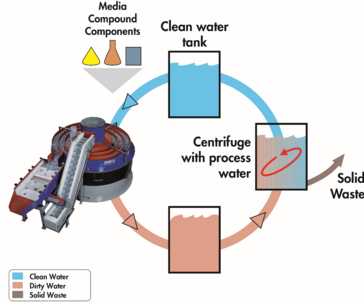
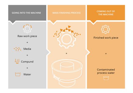
During mass finishing , the process water injected into the finishing machine is contaminated with the chemical ingredients of the compounds , fines from the grinding or polishing media, and metal fines from the work pieces. In case of ball burnishing, when acidic or alkaline compounds are used, the process water can also contain dissolved metals or be alkaline or acidic. Or, for example, when the work pieces are covered with oil from machining or stamping operations, the water can even be contaminated with oil. Rosler has developed a series of closed-loop, water circulation systems using centrifuge technology to remove these contaminants regardless of their origin and allow clean process water to be reused and/or safely discharged. In addition to offering more effective work piece processing, cleaning process water saves money and the environment through reduced consumption, compound usage, disposal costs, and regulations. Mass finishing input and output Environmental Stewardship Depending on the machine size, type, and its application, a single mass finishing machine can use between 10 and up to 250 gallons of water per hour amounting to as much as 2,000 gallons during every 8-hour shift. Considering that the average household uses approximately 140 gallons per day, this is a lot of water that is literally going down the drain. The centrifugal cleaning process separates solids in the form of media and metal fines from the process water without removing the compound. This allows the cleaned process water to be reused in the mass finishing machine. A small amount of compound is consumed to keep the process stable and some water losses occur due to carry-out by the work pieces and evaporation. On average, centrifugal cleaning and recycling of the process water results in water and compound savings of 90 to 95%. Reduced Municipal Regulations Centrifuge technology does not require approval from municipal water authorities since the cleaned process water is reused rather than being discharged into a sewer. Recycling process water saves time by not having to undergo the elaborate discharge approval process. It also eliminates the need for regular water analysis to ensure that the cleaned water going to sewage is indeed in compliance with the legal limits for hazardous materials. https://videopress.com/v/gU0wE8kR?preloadContent=metadata Easy Operation Contrary to conventional waste water cleaning methods, centrifuges are easy to operate and require very little operator involvement. Above all, they require no special training or specialized knowledge. The water level in automatic centrifugal cleaning and recycling systems is automatically monitored, and any water/compound losses due to carry-out and evaporation are made up by fully automatic water/compound dosing units. For applications in conjunction with high-energy mass finishing machines that generate a lot of heat, the centrifuges can be equipped with a special cooling system for controlling the temperature of the process water. In case of semi-automatic centrifuges, an operator must periodically remove the accumulated sludge in the centrifuge drum. This is typically done once every few hours or once per day. In fully automatic centrifuges even the sludge removal is automated. A timer-controlled peeling knife periodically removes the sludge from the drum wall and discharges it into a waiting sludge bin. All the operator must do is empty the sludge bin every few days or, in some cases, weeks. At left, a fully automatic centrifuge during the cleaning cycle is shown. On the right, a sludge discharge peeling cycle is shown. The Rosler Way Centrifugal process water cleaning and recycling makes a significant contribution towards ecologically sustainable production and is a prime example for environmental stewardship in manufacturing. Contact Rosler today to learn how we can improve the efficiency and economic impact of your mass finishing process. Previous posts in the Centrifuge Technology series include: Part 1 – “Water Cleaning Systems Replace Outdated Methods.” Part 2 – “Operational and Economic Benefits of Recycling Process Water.” Part 3 – “Mechanics and Limitations of Water Recycling.” Part 4 – “Pre-Conditions and Consumables Enhance Process Efficiency.” Upcoming posts in the Centrifuge Technology series will include: Part 5 – “Potential Issues and Remedies for Water Recycling.” Sign up for enews alerts to be notified of new posts!
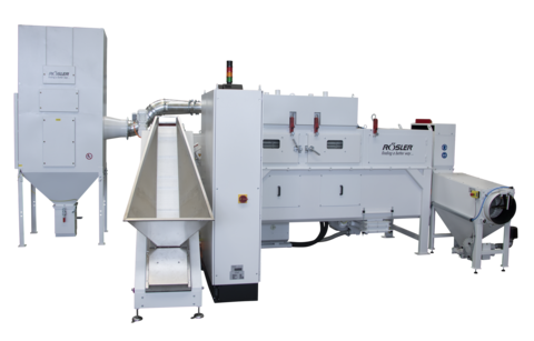
continuous feed looped belt shot blast machine

Top quality – Rösler installs a convincing new plastic de-flashing system at Berker in in Ottfingen

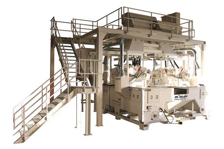
For over 30 years the Berker GmbH & Co KG has been de-flashing plastic components like switching elements, electrical outlet covers, frames, etc., with Rösler shot blast equipment. The company is mainly using continuous feed systems such as loop and flat belt machines. Berker – since 2010 a member of the Hager Group – is one of the leading manufacturers of high-end electrical components – from timeless classical switches to intelligent electrical systems for buildings. The company also supplies switches for electrical appliances and automobiles. Because of an increasing production volume at its Wenden-Ottfingen manufacturing location, in 2018 Berker had to invest in an additional shot blast machine. The new investment was intended to replace an existing continuous feed loop belt system with the latest de-flashing technology. The specifications called for increased capacity and a high equipment availability. After the capacity requirements had been established, Rösler developed a system concept that fully met the customer’s technical and economic demands. Equipped with two direct-drive blast turbines, the new Rösler machine produces excellent de-flashing results combined with an extremely high degree of process stability. This is achieved by a host of technical features like modern PLC controls, an optimized media cleaning and recycling system with vibratory screen and air wash separator, a sensor-controlled media replenishment unit, the automatic replenishment and mixing of anti-static compound, noise protection, an automatic-stand-by module and the Rösler dust collector emitting a minimum of residual dust. An additional bonus was that the new machine design allows the automatic de-flashing of large work pieces, which could not be handled with the old equipment. The above technical highlights convinced the Berker GmbH & Co. KG to purchase the new continuous feed loop belt blast machine RSBS 1702 from Rösler. Unfortunately, the Corona pandemic caused a delivery delay. But the new plastic de-flashing system could finally be commissioned at the customer’s Wenden location in July 2020.

Wet Blasting Technology, Part 3 – Technical Features, Slurry Control Achieve Precise Finishing

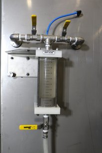
Numerous technical features combine to make wet blasting an effective method of surface finishing . When expertly combined by an experienced finishing expert such as Rosler , this method can achieve precise and repeatable results on a variety of work pieces from a wide range of industries . A general understanding of the essential technical elements of a wet blasting machine will help you select a machine for your specific needs as well as prolonging the efficiency and life of existing wet blasting equipment. Technical Highlights Rosler Wet Blast Schematic The numbered diagram details the wet blast principle and the basic features of a wet blast system. Blast chamber with slurry tank – A mix of media and water is stored in this holding tank found at the bottom of the blast chamber. The chamber is made of stainless steel. Compressed air – Approximately 70 PSI of compressed air accelerates the slurry. Blast gun(s) – One or more guns accelerate the slurry supplied by the slurry pump with compressed air. Blast media feed – Media enters the machine. Slurry pump – This high-powered mechanism transports the slurry to the blast gun(s). Larger wet blast systems can be equipped with multiple pumps. Slurry agitator (stirrer nozzle) – In order to keep the media suspended in the water, the slurry pump diverts some of its flow to a stirrer nozzle placed in the tank to agitate the mix of water and abrasives. Overflow – Small media particles, dirt, and other contaminants tend to stay suspended and are skimmed off and sent to the filtration unit. Water filtration system – Media particles and debris skimmed off the water’s surface must be passed through a filtration system to separate still usable media and process water from waste. Common filtration methods include hydro cyclones, weir tanks, bag filters, paper band filters, and semi- and fully automatic centrifuges. Filtered water – Once processed by a water filtration system, water is returned to the slurry tank and reused. Exhaust vent – The water mist mixed with media fines and other small particulates is removed from blast cabinet by suction fan-equipped filters. Controlling Slurry Concentrations Depending on the specific wet blast process, the typical concentration of abrasive media in the slurry ranges from 10 to 40% by volume. Establishing the ideal concentration usually requires more or less extensive processing trials. During the blast process the media wears by becoming smaller or fracturing and must be removed from the system. To make up for this loss, good media must be added. To consistently achieve the desired high-quality blasting results, the established slurry concentration must be maintained within a very tight tolerance range of 1-2%. This can be done by visual inspection of the viewing glass and manually adding media as needed. However, in larger blast systems the slurry concentration is controlled automatically with an ultrasonic level sensor, a weighing system, or continuous density measurement. Adding media to the desired concentration level can be done manually or through an automated, PLC controlled media adder. Manual slurry concentration measurement unit The Rosler Way Building standard and custom wet blasting equipment to deliver precise, repeatable results is the Rosler Way. Contact us to learn how we can solve your surface finishing challenges and to request a FREE sample processing in one of our global test centers . The complete Wet Blasting Technology Series includes: Part 1 – “Wet Blasting Gently Delivers Dramatic Finishing Results.” Part 2 – “Comparing Attributes, Advantages to Dry Blasting.” Part 3 – “Technical Features, Slurry Control Achieve Precise Finishing.” Part 4 – “Typical Wet Blasting Applications.” Part 5 – “PureFinish® Offers Food-Grade Excellence.” Sign up for enews alerts to be notified of all Rosler blog posts!
crankshaft shot blast machine RKWS 3/4

Rösler presents a convincing equipment maintenance concept to thyssenkrupp Gerlach GmbH

For a company to become and remain a leader in its respective industry demands that it constantly reviews and improves its products and the underlying manufacturing processes. With its competence and knowhow in materials for drive trains, chassis and automobile manufacturing equipment the automotive division of the world renowned thyssenkrupp AG is a significant contributor towards the technical progress and efficiency of motor vehicles. The thyssenkrupp Gerlach GmbH plant in Homburg, Germany, is a leading partner for the development of automobile engine components and offers a full service package ranging from the design of specific components, the fabrication of prototypes to full-scale production. To improve the cost efficiency at its Homburg plant and to meet all the customer requirements, in 2016 the company installed its high-tech “production line 19” for forged crankshafts for engines with 1 to 4 cylinders. For this line the engineers of the surface refinement specialist Rösler developed an innovative shot blast equipment concept that was so convincing that the thyssenkrupp management placed an order for the new Rösler “RKWS” crankshaft shot blasting system. The fastest crankshaft forge shop in the world At the beginning of the manufacturing sequence the bar blanks are cut to length. Before being shaped in a 6,500 ton press, they are heated in an induction oven. In a last step the crankshafts undergo a blast cleaning process in a shot blast machine. For the last operation the Rösler engineers developed a unique equipment concept that allows the handling of different work piece sizes without time-consuming retooling of the work piece holders. This helped reduce the cycle time to less than 10 seconds, which in turn allowed the manufacturing operation to be run in continuous flow. The result of the comprehensive cooperation of thyssenkrupp with Rösler and all the other partners was the fastest, most modern crankshaft forge shop in the world that produces a finished component for its customers every 7.5 seconds. The “RKWS” system – designed for long life and easy maintenance The three blast chambers and the work piece load/unload chamber are arranged in a circle around a rotary drive equipped with an asynchronous servo motor with an extremely high overload reserve. The blast media is accelerated and thrown by Rösler Gamma blast turbines equipped with the worldwide unique “Y” design of the throwing blades. The critical wear components of the Gamma turbines are not made of chilled iron castings, typically used in conventional turbines, but of forged tool steel. This results in a much longer uptime of, for example, the throwing blades. The blade curvature produces a much higher throwing speed than straight throwing blades. In addition, the symmetrical “Y” design allows the use of both blade sides. The combination of more wear resistant material and the blade geometry result in an up to 3 times longer usable blade life. Another feature of the Gamma turbines is their easy maintenance. Turning the blades around or exchanging them can be done from the top of the turbine housing without having to dismount impeller, control cage and the media inlet tube required with conventional turbines. The RKWS is equipped with 12 Gamma turbines, each with an installed power of 22 kW. The turbines, evenly placed on the three blast chambers, are throwing the large steel shot onto the entire surface area of the crankshafts with a speed of 80 meters pe second. This results in a complete removal of forging scale and other surface contaminants. By utilizing highly wear resistant material for all components exposed to the large cast steel shot and the removed forging scale, the Rösler engineers ensured that the RKWS shot blast system was not exposed to excessive wear. The three blast chambers were lined with wear resistant hardened steel. The media augers were made from special steel that is predominantly utilized in the mining industry. Technical characteristics of this material are its extreme toughness and its remarkable hardness of 600 Vickers providing it with a considerable structural strength. Smart maintenance concept The entire volume of customer orders is handled by the new “production line 19” within 21 shifts per week. This poses a considerable organizational challenge for the thyssenkrupp Gerlach GmbH maintenance department. For managing the time for the equipment upkeep the maintenance team, led by Markus Kania, decided to introduce a TBM system (time based maintenance). Within a pre-determined time span a recurring time window is defined for all inspection and maintenance activities as well as any required repairs including the replacement of spare parts. The time management allows requisitioning all repair materials in advance and facilitates the effective assignment of the maintenance personnel at thyssenkrupp Gerlach GmbH in Homburg. Adequate spare parts stock allows sustainable long-term planning Planning certainty for the entire manufacturing line, along with a constant high product quality, is a high priority at thyssenkrupp Gerlach GmbH. For this reason, the project leader, Markus Kania, made sure that besides a forward looking preventive maintenance the essential wear and spare parts for all machines were determined jointly with the equipment suppliers and stocked on site in Homburg. To define the specific requirements for the crankshaft shot blast machine the customer relied on the experience of the Rösler service department. Based on the customer specifications the service experts at Rösler conducted a risk and wear analysis. For this purpose they utilized a ultra-modern simulation of the blast media recycling process that allowed them to determine the wear intensity for every single component. Based on the results of the analysis a comprehensive list of recommended spare parts was prepared including wear parts such as protective wear plates, etc. „The professionalism displayed during the preparation and presentation of the list of recommended spare parts with assembly drawings and 3D models was so impressive that after a brief internal discussion at thyssenkrupp we placed an order for the recommended wear and spare parts”, explains Markus Kania. He continues “With the maintenance and spare parts concept we minimize the risk of downtimes and save time and money during the procurement process. This will be a significant contribution towards strengthening our competitive advantage at our Homburg location”. For special situations the maintenance team of the “PL 19” can rely on the quick response by the Rösler service department. The Rösler manufacturing depth with short production times and express delivery of practically all spare parts is no doubt a great advantage. The excellent cooperation with Rösler during the entire project was the main reason that thyssenkrupp Gerlach GmbH decided to work again with the surface refinement specialist from Memmelsdorf for a new investment project at the Homburg location. This time the customer plans to establish a new production line for the manufacture of axles and crankshafts for heavy-duty transport vehicles.

Centrifuge Technology, Part 1 – Water Cleaning Systems Replace Outdated Methods

Before the “dirty” process water coming from a mass finishing operation can be discharged to sewage, it must be cleaned to meet the legal discharge limits for hazardous materials. Likewise, for cycling the water back to the mass finishing process, the process water must also be cleaned. Uncleaned process water would cause a mass finishing process to collapse very quickly. Rosler has more than 80 years of surface finishing expertise. In that time, we’ve developed countless efficiencies in both the design of our equipment and the processes they support. Centrifuge technology has long been an effective and cost-efficient tool, not only for cleaning the process water, but also for reusing it for the actual mass finishing operation. Previous Cleaning Methods To a large extent, this technology has replaced traditional waste water cleaning methods. Until recently, the most common cleaning systems for mass finishing applications were settlement tanks and flocculation (“floc & drop”) systems. Settlement Tanks In settlement tanks the “dirty” water is collected in big tanks. The solid particles suspended in the liquid settle to the bottom over time, creating a time-consuming and rather messy cleaning method. Above all, this method does not meet the legal discharge limits for removing contaminants from the solution, including: COD values (chemical oxygen demand). Solid particles. Oil. Metal. As a result, settlement tanks are rapidly being replaced by more environmentally friendly cleaning systems. “Floc & Drop” Systems “Dirty” process water is collected in a large tank in “floc & drop” systems. Flocculants are added to the water to coagulate the tiny solid particles and emulsified oil droplets into larger flocs. These flocs sink to the bottom of the tank and are then pumped to a filter press or bag. Unlike settlement tanks, water discharged from “floc & drop” systems meets legal standards and can be discharged to sewage. These systems are very labor intensive and often rely on operator to ensure all steps are taken to meet the authorized discharge limits. Other Methods & Special Uses Evaporators and membrane filtration systems are occasionally used for mass finishing operations as well. Except for settlement tanks, which are pretty much obsolete, the other waste water systems mentioned still have a place in mass finishing operations particularly for special applications. In general, these systems are costly and somewhat difficult to operate compared to centrifuges. Above all, non-centrifugal methods do not allow the recycling of the cleaned process water for reuse in the respective mass finishing process! Unique Capabilities In recent years, centrifuges (also called centrifugal filters) have proven to be the most effective, cost-efficient, and ecologically sustainable cleaning systems for the “dirty” process water generated in mass finishing operations. Centrifuges are very easy to handle and require no special knowledge to operate them. Furthermore, they require no permits from local water authorities. Centrifuge Recycling Schematic They also excel when it comes to cost savings and consumption. Centrifuge technology can reduce the water and compound consumption in mass finishing operations by up to 95%. This saves not only money but makes a substantial contribution toward environmental sustainability in manufacturing. In short, cleaning centrifuges represent a rare industrial equipment category, where economic benefits go hand-in-hand with ecological objectives and environmental stewardship! The Rosler Way “Finding a better way…” is more than a motto at Rosler; it’s our mission. The use of centrifuge technology in mass finishing operations is just one of our many innovations. Contact us today to learn how we can help solve your unique surface finishing challenges. Previous posts in the Centrifuge Technology series include: Part 1 – “Water Cleaning Systems Replace Outdated Methods.” Part 2 – “Operational and Economic Benefits of Recycling Process Water.” Part 3 – “Mechanics and Limitations of Water Recycling.” Part 4 – “Pre-Conditions and Consumables Enhance Process Efficiency.” Upcoming posts in the Centrifuge Technology series will include: Part 5 – “Potential Issues and Remedies for Water Recycling.” Sign up for enews alerts to be notified of new posts!

Rösler China and HUST announce their strategic cooperation for the development of forward-looking surface treatment technologies for jet engine components

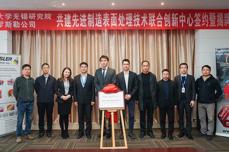
„Finding a better way” is an essential part of the corporate philosophy of Rösler that is practiced daily. This is highlighted by the recently concluded cooperation agreement of the Chinese Rösler subsidiary, Rosler Surface-Tech (Beijing) Co., Ltd., with the renowned Huazhong University of Science and Technology, WUXI Institute (HUST) in the field of forward-looking surface treatment technologies for jet engine components. As one of the top 10 universities in China, the HUST is known for numerous successful research projects in the Chinese high-tech sector. Its research focus is on the fields of aerospace, medicine and robotics. Since 2019 HUST also works on innovative manufacturing technologies for jet engines and the adaptation of these technologies to series production. The new "Joint Innovation Center for Advanced Manufacturing Surface Treatment Technology" is financed by HUST, AECC and the WUXI government. On the technical side it is supported by Rösler China. Goal of the new innovation center is the development of future-oriented surface refinement methods for BLISKs and compressor, as well as, turbine blades. During a joint visit on the occasion of the opening of the innovation center, Yiling Sun, General Manager of Rösler China, demonstrated a linked system in the form of a rotary vibrator without inner dome (R 420 DL), a transport belt (R 360/3000 FB/T), a vibratory separation unit (R 12/6 SM-E) and a process water cleaning centrifuge (Z 1000 ASS-II-Turbo) to the guests and explained the entire finishing process in detail. On this occasion it was agreed that further investments will be made in the innovation center. Stephan Rösler, President & CEO of the Rösler Oberflächentechnik GmbH, explains: „The strategic partnership with the Huazhong University of Science and Technology allows us to consolidate and expand our outstanding position in an extremely important market segment. It will enable us to offer even more innovative solutions in the field of equipment and process development for the aerospace industry”.

Wet Blasting Technology, Part 2 – Comparing Attributes, Advantages to Dry Blasting

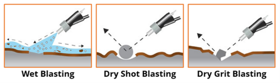
Unlike dry blasting in which only solid abrasive media is used, wet blasting processes use a slurry in which the media is embedded in water. This greatly cushions the impact energy on the work pieces, providing gentler, yet effective results for delicate work pieces. As the utilization of wet blasting increases, Rosler reminds manufacturers to review their traditional, dry shot blasting applications and consider if wet blasting could provide additional efficiencies, reduced costs, and better results. Understanding the Differences As in any surface finishing process, the starting condition of the work piece, its material composition, shape, and final finish largely dictate which finishing application is most appropriate. Understanding how the application changes the work piece is a key consideration. In wet blasting, the water cushions the impact of the media, leaving only slight or no deformation on the surface of the work piece. Due to a much higher impact energy, dry blasting with shot can cause substantial deformation of the work piece. Using grit with dry blasting creates an even higher impact energy than shot. The sharp edges of the grit media rip open the surface of the work piece. Advantages of Wet Blasting In addition to gentler delivery of media to the work piece, wet blasting technology offers several advantages. Benefits apply to the work piece itself as well as the environment the process is housed within, including: No dust – Wet blasting does not generate dust and, therefore, no dust collectors or extra environmental precautions are required. No fire/explosion risk – Fire prevention and explosion protection equipment is not required since wet blasting does not present a fire or explosion risk during operation. No media impingement – Unlike dry blasting which poses a risk of media particles embedding in the work pieces surface, causing premature corrosion and problems, with coating or painting, impingement does not occur with wet blasting. No bending/warping of heat-sensitive pieces – Dry blasting generates a lot of heat which, combined with high impact energy of the media, can cause delicate parts with thin walls to bend and warp. Wet blasting does not. Deep surface cleaning – Wet blasting provides deep surface cleaning by removing and immediately washing away any dirt and contaminants adhering to the work pieces. Handling limited amounts of grease/oil – While dry blasting requires work pieces to be completely free of grease and oil due to the risk of contaminating the blast media and causing a fire hazard, wet blasting can accommodate oil and grease to a certain degree by injecting a degreasing additive into the slurry. Exceptionally fine, uniform finishes – Wet blasting generally produces a lower surface roughness than dry blasting without jeopardizing the overall cleaning effect. Cosmetic blasting efficiency – Wet blasting is an ideal way to create a matte, yet very smooth cosmetic finish. Holding tight tolerances – The less abrasive nature of wet blasting and lack of warping/bending allows for much tighter tolerances to be held and is especially crucial when finishing delicate pieces with thin walls. Adjustable blast intensities and media concentrations – By increasing or decreasing the media concentration in the slurry and the slurry and air pressure, the wet blasting intensity can be easily adjusted. Wet Blasting Gun Schematic The Rosler Way As a trusted surface finishing source for more than 80 years, Rosler combines hard-earned expertise and cutting-edge technology to deliver precise, repeatable wet blasting machinery, consumables , and precise finishes. Consider the benefits of wet compared to dry blasting and contact us to find the right process for your surface finishing needs as well as FREE sample processing in one of our global test centers . The complete Wet Blasting Technology Series includes: Part 1 – “Wet Blasting Gently Delivers Dramatic Finishing Results.” Part 2 – “Comparing Attributes, Advantages to Dry Blasting.” Part 3 – “Technical Features, Slurry Control Achieve Precise Finishing.” Part 4 – “Typical Wet Blasting Applications.” Part 5 – “PureFinish® Offers Food-Grade Excellence.” Sign up for enews alerts to be notified of all Rosler blog posts!

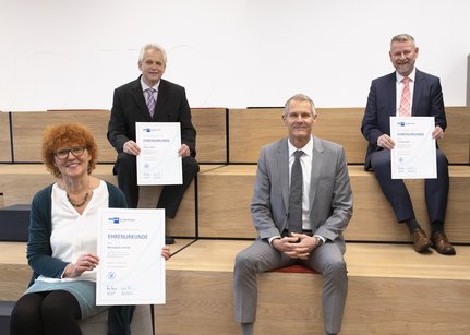
Auch in Zeiten von Corona: Rösler ist stolz auf seine Jubilare

Die Rösler Oberflächentechnik GmbH dankt 48 langjährigen Mitarbeiterinnen und Mitarbeitern in diesen herausfordernden Zeiten für insgesamt 975 Jahre Treue und Loyalität – die Feierlichkeiten fanden im kleinen Rahmen unter strenger Einhaltung der Hygienevorschriften statt. Die feierliche Ehrung der Betriebszugehörigkeit und die Verabschiedung von Mitarbeitern in den Ruhestand hat bei Rösler eine lange Tradition. Angesichts der anhaltenden Corona-Pandemie musste die traditionell auf Kloster Banz stattfindende Feierlichkeit dieses Jahr leider abgesagt werden. Doch um die Wertschätzung gegenüber den Jubilaren zu zeigen, fanden die Ehrungen in Kleingruppen durch die entsprechenden Führungskräfte zu separaten kurzen Terminen unter Wahrung der erforderlichen Hygieneregeln statt. In diesem Zusammenhang dankten die Führungskräfte im Namen der Firma Rösler allen Mitarbeiterinnen und Mitarbeitern für die jahrzehntelange Treue und deren Engagement, insbesondere in so schwierigen und unsicheren Zeiten wie diesen. Die Rösler Oberflächentechnik GmbH gratuliert … zum 40-jährigen Betriebsjubiläum: im Werk Memmelsdorf: Bernadette Hertel, Frank Möller, Johann Wendler, Rüdiger Böhm sowie Karin Schaarschmidt aus dem Werk in Hausen. … zum 25-jährigen Betriebsjubiläum: Dirk Neupert, Ralf Müller, Jan Reinmann, Reiner Kirchner, Bernd Klett, Jürgen Geisler, Heiko Vogel, Georg Bornschlegel, Friedrich Steinepreis, Gerhard Wagner, Thomas Dillinger, Daniel Bätz, Uwe Michael, Bodo Helmert, Andreas Ereth, Denis Dorittke, Irene Walther, Uwe Lautensack, Thomas Dreßel, Gerhard Edelmann – alle tätig im Werk Memmelsdorf – sowie Alex Britner, Eduard Neimann und Heiko Traut im Werk Hausen. … zum 10-jährigen Betriebsjubiläum: im Werk Memmelsdorf: Jakob Koch, Florian Müller, Kathrin Bätz, Matthias Voigt, Leo Higgs, Andreas Schubert, Günter Elflein, Jürgen Buss, Ingo Staak, Sylvia Eichenberg, Michael Klemmt, Werner Vießmann, Igor Ratz, Daniel Jahn, Jessica Ebert, Sonja Tal, Daniel Schramm, Rainer Sauerbier, Alexander Jost und Björn Nesbor. Langfristiges Erfolgsdenken als Teil der Rösler DNA Stephan Rösler, Geschäftsführender Gesellschafter der Rösler Oberflächentechnik GmbH, bedankte sich darüber hinaus in einem schriftlichen Weihnachtsgruß bei allen Mitarbeiterinnen und Mitarbeitern für deren Einsatz und Loyalität. Trotz der momentan schwierigen wirtschaftlichen Situation, in welcher viele Unternehmen ihre Produktion und Neuinvestitionen deutlich zurückfahren und die Firma Rösler dadurch bedingt einen deutlichen Umsatzrückgang zum Vorjahr verzeichnen werde, ist es sein erklärtes Ziel, die Rösler Gruppe für eine langfristige, nachhaltige und erfolgreiche Zukunft aufzustellen. So wurden zuletzt zukunftsweisende Investitionen, wie z. B. in den Bereichen Compoundfertigung, Logistik, Keramikfertigung, mechanische Fertigung, Rösler Academy, Kunststoffschleifkörperfertigung sowie in ein neues Betriebsrestaurant oder in Photovoltaikanlagen, angestoßen. Auch im jüngsten Geschäftsfeld AM Solutions, welches sich mit den Herausforderungen des 3D-Drucks beschäftigt, konnte zuletzt ein prestigereiches Projekt mit dem renommierten Druckerhersteller HP erfolgreich umgesetzt werden. Er betonte zwar, dass man sicherlich keinen Einfluss auf alle Dinge habe, aber dass er und sein Führungsteam ihr Bestes getan hätten und auch weiterhin tun, um die Zukunft der Firma Rösler erfolgreich und nachhaltig zu gestalten.
Mass Finishing Media, Part 3 – Why Discharging Undersized Media, Maintaining Media Levels Are Crucial

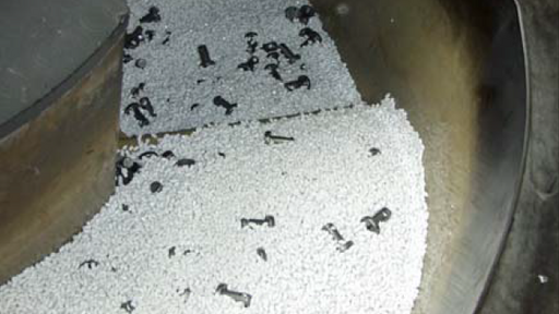
Mass finishing processes are effective because the motion of media against work pieces transforms the surface of the work pieces. The deflashing , descaling , edge rounding , polishing/smoothing , cleaning/oil removal/degreasing , and/or grinding effects change the surface of the media itself along with the work pieces. As a result, media wears down over time, losing its shape, size, and effectiveness. Known as undersized media, this worn media must be discharged and replaced with fresh media to ensure proper processing and safety. Whether a process uses ceramic , plastic , or polishing and drying media , Rosler stresses the importance of monitoring media levels and the mix of new and worn media for precise and safe mass finishing results. Worn Media Reduces Process Effectiveness Over time, media wears and becomes smaller. This undersized media can throw a process completely out of balance in several ways, including: Media lodging in the work pieces which could cause safety issues later in the process. Clogging drains within the finishing machine and causing flooding. Failing to meet finishing standards. Increasing required finishing times. Poorly selected media shapes and sizes can lead to problems such as ineffective finishing and media lodging within the work pieces as shown. Timely and effective discharge of the undersized media and replacing it with new media is, therefore, critical for the stability of any mass finishing process. Discharge can be done continuously by building suitable undersize screens into the actual mass finishing machine or in the vibratory screening unit. To prevent media clogging, undersize screens themselves must also be monitored. If lodging or clogged drains occur over time, undersize screens with larger holes should be installed. Undersized media screens allow media that is too small to be effective any longer to fall through screen holes and remove it from the media mix. In rotary vibrators with internal separation, the undersized media discharge can sometimes be inefficient. Running the complete media charge through an external vibratory screening machine equipped with special undersize screens every few days provides effective removal of undersized media and helps maintain the optimal media mix. New Media Offsets Undersized Loss Removing undersized media must be offset by the addition of new media. Without timely replacement, the media level in the machine will become lower, which may drastically impact the finishing process in several ways. Decreases in the media-to-work piece ratio will cause nicking and scratching of the work pieces. A higher portion of smaller media in the machine will prevent the process water from getting drained from the machine resulting in dirty work pieces. In vibratory machines, the spiral movement of the media/work piece mix will collapse if the media level drops too low resulting in poorer finishing results and longer cycle times. The media level in this rotary vibrator is too low In all cases, the process will completely collapse within a few days—sometimes within a few hours! Depending on the machine and media type, new media should be added at regular intervals such as with every work piece batch, once every few hours, or once a day. Your media supplier should be able to help you with frequency based on test batches and careful monitoring. Equipment updates may also be available to automate media replacement such as the installation of a timer- or weight-controlled media replenishment system to help maintain the right media working mix. The Rosler Way As a supplier of mass finishing media and machines, Rosler has the expertise to both engineer unique applications and supply the consumables and advice necessary to keep them operating efficiently. Contact us to learn how we can solve your unique challenges and meet your ongoing needs. The complete Mass Finishing Media Series includes: Part 1 – “Don't Navigate the Complex Selection Process Alone.” Part 2 – “Tips for Measuring Media-to-Work Piece Ratio.” Part 3 – “Why Discharging Undersized Media, Maintaining Media Levels are Crucial.” Sign up for enews alerts to be notified of all Rosler blog posts!
processing bowl

Radiusing of tooling components with the drag finishing technology

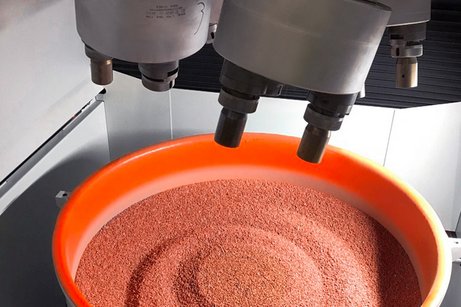
Radiusing of tooling components with the drag finishing technology To date the voestalpine Rotec GmbH, a global leader in the manufacture of precision steel pipes and tubes, has been using a manual process to place a radius on its stamping tools. Within the framework of its continuous process optimization program the company replaced this manual operation with an automated Rösler drag finishing system R 4/700 SF. With the single piece dry drag finishing process the usable life of the stamping tools can be at least doubled. For some tools the uptime can even be increased by a factor of ten. For this reason, the return on investment period (ROI) is well below two years. With eleven manufacturing locations in Europe, North-America and Asia the voestalpine Rotec is a globally operating company that is specialized in the manufacture, refinement and marketing of precision steel pipes and tubes. Since the company belongs to the internationally operating steel and technology corporation voestalpine, the customers have direct access to comprehensive knowhow ranging from steel liquification to the complete pipes and tubes. The development of innovative products and manufacturing technologies takes place in four divisions. Within the corporate structure the voestalpine Rotec, headquartered in Krieglach, Austria, belongs to the metal forming division. At this location the company manufactures primarily belt tensioning tubes for the automobile industry. The complex manufacturing equipment for making pipe and tube components is also designed and built at the same location. Hannes Winkler, assistant to the plant manager at voestalpine Rotec and responsible for process optimization, explains: „To be able to make our products at internationally competitive costs, our company is utilizing continuous improvement processes.” Cost reduction by increasing the usable life of tooling Even before wear became visible, stamping tools like arbors and die plates had to be replaced because of minor fracturing at the edges. Frequently the edges were reworked by hand. But this did seldom extend the usable life of the tools. With around 50 million manufactured components per year tooling supply was a significant cost factor. Therefore, it was not surprising that the process optimization specialist was looking for an automated, repeatable edge radiusing process for prolonging the service life of the tooling. Cost-efficient dry processing in a drag finisher Edge radiusing of the tools is an ideal application for the drag finishing technology. This unique mass finishing system allows the precise, targeted surface finishing of high-value, complex work pieces. Exactly defined process parameters guarantee absolutely repeatable finishing results. “From my previous occupation at a supplier of motor sport components I knew that Rösler Oberflächentechnik builds such equipment. That is why I contacted Rösler first. Of course, we also contacted other suppliers of mass finishing equipment and asked them to run processing trials for us”, continues Hannes Winkler. In the end the customer chose the R 4/700 SF system, because Rösler was the only supplier, who could offer a dry finishing process for the tools. Hannes Winkler adds: „The dry solution eliminated the process water cleaning system required with the wet processing solution. This reduced not only the capital expenditure but also resulted in lower operating costs. Of course, the quality and long service life as well as the high availability of the Rösler equipment also played an important role in our decision.” Automated finishing that is perfectly adapted to different tools At the heart of the compact, plug-and-play drag finisher is a carousel equipped with four rotary spindles, each spindle allowing the mounting of three work pieces. The carousel and the rotary spindles are outfitted with separate drive motors allowing the setting of totally different rotary speeds for carousel and spindles. The processing bowl is filled with processing media, which in this particular application consists of crushed walnut shells and aluminum oxide. A vibratory motor mounted below the processing bowl ensures the optimum mixing of the processing media. Required bowl changes can be quickly carried out with a forklift truck. For the actual process the tools to be finished are manually mounted to specially designed work piece fixtures, which in turn are attached to the spindles equipped with quick-connect couplings. To facilitate this operation, the operator moves the spindles to the load/unload station with the touch of a button. This allows quick, ergonomic and simple loading/unloading of the work pieces. Once the respective processing program, stored in the programmable system controls, has started, the carousel with the spindles is lowered so that the rotating spindles are immersed in the processing media. Carousel and spindles are moving clock- and counterclockwise at the defined rotary speeds. At the midpoint of the processing cycle – depending on the tools to be finished, the total finishing time varies between 15 and 45 minutes – the rotary direction is usually changed. This guarantees an even radiusing of the tool edges on all sides. Continuously growing work piece spectrum shortens the amortization period Initially it was planned to use the drag finisher for five frequently used tool types. Hannes Winkler reports: „The new mechanical drag finishing system produced such good results that the usable life of these components could be practically doubled. And in some instances it could even be increased by a factor of ten. Since commissioning the drag finisher about six months ago, we have increased the spectrum of work pieces to be finished mechanically to around 20 different tool types. This helped reduce the amortization period to well below two years. By continuously adding additional work pieces, the amortization time will decline even further”. This positive experience led the voestalpine group of companies to list Rösler as the exclusive supplier for this particular finishing application. Besides the mechanical edge radiusing of additional tool types, the process optimization specialist is also considering a polishing application. Hannes Winkler concludes: „At the moment we are conducting processing trials. If the results are as we expect, we will purchase a second processing bowl with the required processing media. A key advantage of the Rösler drag finisher is that processing bowls can be easily exchanged allowing us to quickly switch from one application to another”.

Monitor Wear Linings to Maintain Process Efficiency, Increase Equipment Longevity

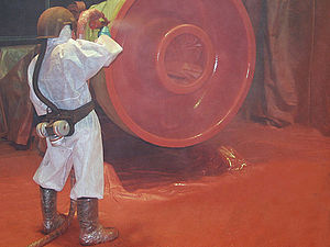
Mass finishing machinery is a major investment for most companies. Proper maintenance and preventative repairs over the life of these useful and necessary machines will greatly improve the return on such investments, drive productivity, and extend the working life of the equipment itself. Rosler stresses the need to regularly inspect the linings of vibratory tubs and troughs to identify repairable issues before permanent damage occurs. Media-Induced Wear To effectively finish work pieces, media must be matched to the specific finishing task and initial state of a work piece. For example, media used for deburring/edge radiusing and surface grinding can be very abrasive. If not properly protected by a suitable wear lining, the steel construction of a work bowl would be completely worn through in a few hours by contact with the media and work pieces. Polyurethane and, to a certain degree, rubber are excellent lining materials providing wear protection for thousands of operating hours. Even these materials wear though and must be periodically replaced with a new lining. (More information about specifying liner materials is available in a previous blog post .) Maintaining Process Stability Checking your work bowl lining for wear and replacing it in a timely manner is essential for the stability of your mass finishing process as a whole. In addition to worn work bowls, failure to ensure a proper protective lining can create other problems including: Work pieces getting stuck in the machine and, therefore, jeopardizing the integrity of different work piece batches. Media, water, and process chemicals can leak from the machine if the metal processing bowl is worn through and holes or cracks appear. Severe machine malfunction can occur when media or parts can get trapped in worn spots during the separation phase when the finished work pieces are separated from the media. Damage to the work bowl that is beyond repair, causing an unnecessary downtime and requiring costly replacement parts. A weakened bowl can crack and make the entire machine unusable Check your bowl lining at least monthly for wear or rips. Especially the areas around drains, the parts loading chute, and around the unload areas will see the highest wear. The “nail test” makes checking the liner thickness easy. Push a nail trough the liner until you hit the base metal and record the thickness of the liner. Keep track of the liner thickness over time to predict when you will need to replace your liner. Just as optimal media mix must be regularly monitored, so must the condition of a work bowl. If not, the entire process and downstream operations may suffer. Reline Expertise This work bowl is being relined with sprayed‐on polyurethane at a Rosler reline shop. Rosler maintains a shop offering reline services for work bowls of all types and makes. With the unique Rosler ThermoStrip procedure, we can patch and repair worn work bowls to restore process efficiency and extend the life of your equipment whether Rosler designed it or not. The Rosler Way Our worldwide network of service providers is positioned to provide expert service and guidance. Contact us to discuss how we improve your process and increase the lifespan of your equipment.
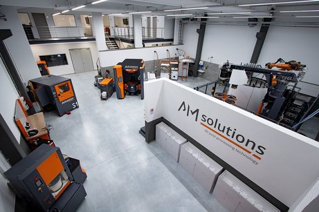
test lab AM Solutions

New technology and test center for Rösler brand AM Solutions – 3D post processing technology

The ideal environment for process and product development for post processing of 3D printed components The new technology and test center of AM Solutions – 3D post processing technology represents a significant milestone in the development of processes and products for the post processing of products created with AM methods. The new center is outfitted with state-of-the-art engineering software and various 3D printing systems. However, the main focus is on an exceptionally well-equipped post processing section, where AM Solutions – 3D post processing technology can demonstrate an impressive range of machinery for post processing of 3D printed components. Additive manufacturing allows the quick and flexible production of metallic or plastic components with precisely defined material characteristics. All these components have one thing in common: Their surface requires different kinds of finishes, which must comply with the most stringent finishing specifications. These requirements pose a special challenge for the post processing of 3D printed components. AM Solutions – 3D post processing technology is meeting this challenge head-on with its new, generously equipped technology and test center at the company’s location in Untermerzbach. State-of-the-art technologies along the complete AM process chain under one roof In its new test center with a total area of 400 square meters, the Rösler division specializing in 3D post processing solutions, can demonstrate the complete process chain of additive manufacturing. Manuel Laux, Head of AM Solutions – 3D post processing technology, explains: “It is our declared goal to develop the best possible process solutions for our customers. To do this we must be able to fully understand every detail of the additive manufacturing process and must actually be in a position to demonstrate the various manufacturing stages. Only with such a hands-on approach will we be able take into account all the facets of additive manufacturing.” The new test center is not only equipped with the latest engineering, printing and post processing hard- and software, but the actual building was also carefully prepared, For example, suitable air intake and venting systems were installed to maintain exact temperature and humidity levels in the pressure area. For engineering and topology optimization the center is utilizing NX CAD software from Siemens. The 3D scanner Atos from GOM allows quick and precise optimization of engineering operations. In addition, it is also utilized for quality control. The printing sections are strictly separated by material categories, and the actual printing equipment is placed in vibration absorbing areas. Metallic materials are printed with an EOS M 290 system, whereas for the creation of plastic components a Polyjet printer Objet 260 Connex 3 from Stratasys, a Multi Jet Fusion printer HP Jet Fusion 3D 5200 and a FDM printer are available. To allow test trials for the development of optimum, automated post processing solutions and to select the most suitable equipment, AM Solutions – 3D post processing technology installed its own post processing equipment line in the form of the models S1, S2 and S3 as well as M1, M2 and M3. Moreover, the test center is equipped with various post processing systems from the AM Solutions partners GPAINNOVA and PostProcess Technologies. These include a GPAINNOVA DLyte 100 and the first installation in the world of a DLyte 10.000. In addition, the DEMI, DECI, DECI Duo and Rador from PostProcess Technologies are available for test trials. With such a comprehensive equipment portfolio the new technology center is an ideal partner for the efficient specification and development as well as optimization of customer specific processes and products for post processing of 3D printed components. This includes unpacking, removal of support structures, stripping of loose as well as sintered-on powder from the work pieces, but also general cleaning, surface smoothing, edge radiusing and, even polishing.