Solution Finder
SOLUTION FINDER

Ihr Wegweiser durch die
Rösler-Produktwelt

Mit nur wenigen Klicks finden Sie die richtige Maschine fĂŒr Ihre Belange!

Ergebnisse: 237 Artikel - 54 Produkte

Foundry-Specific Shot Blasting Achieves Increased Efficiency

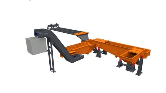
Replacing a shot blasting machine for a long-time customer requires finding a better way to deliver efficient finishing in a faster, smaller, and more maintenance-friendly way. That’s exactly what Rosler delivered when Linde Material Handling (Linde) returned to us for a shot blasting upgrade. Linde is a supplier of forklift trucks and warehouse equipment and also provides technical intralogistics solutions and services. With a sales and service network spanning more than 100 countries, the company has a global footprint. For this particular partnership, Linde’s foundry in Weilbach, Germany, challenged Rosler to supply a new shot blasting system capable of finishing and maneuvering the counterweights it manufactures for forklifts. Our solution was a sturdy foundry version of a continuous hanger shot blast machine known as the RHBD 22/27-F. The Situation Linde continuously strives to improve its manufacturing operations. As such, the new machines had to accomplish several goals, including faster processing, more flexible material flow, optimized utilization of available space, improved access to all critical maintenance areas, and increased overall efficiency. Working closely with the Linde project team, Rosler identified ways to optimize the material flow and increase overall flexibility within the shot blasting technology utilized. To fulfill the demand for better utilization of space, these technology enhancements were built into a customized version of the RHBD continuous feed spinner hanger blast machine. The Solution The newly created machine is setting new standards for surface finishing in the foundry industry, and its fully automatic and flexible operation integrates seamlessly into Linde’s existing manufacturing systems. Within the scope of the newly laid out material handling process, raw castings are deposited in a specially reserved and clearly marked staging area in front of the blast machine’s inlet chamber. An operator then manually positions the castings and prompts the system to transport the work pieces through the shot blasting chamber. Different PLC programs define and store specific shot blasting and transporting parameters based on the specific work piece being processed. This ensures that the various counterweight types are perfectly clean and free of residual molding sand after shot blasting. The work pieces also display highly homogeneous surface roughness and the typical casting structure even after subsequent painting. The Process After work pieces have been manually positioned in the staging area, trolleys on a power and free work piece transport system pick up and carry them through the different machine sections, including the inlet, blast, and outlet chambers according to predetermined indexing time intervals. A rendering of the RHBD 22/27-F’s blast media return and cleaning systems Despite being housed in a very tight space, Linde’s new RHBD is easily accessible for maintenance thanks to placing the return system for blast media and sand underneath the shot blasting machine. The system also includes a return system for sand left on the staging area after manual positioning. Both collections of sand and debris as well as any sand and blast media from the outlet chamber are transferred to the central screening hopper below the blast chamber where sand clumps, burrs, and metal flashings are separated, transferred to a sturdy Z conveyor belt, and discharged from the machine. The remaining sand/media mix is transported to an elevator and into a highly efficient media cleaning system. Consisting of a dual-stage magnetic separator and an airwash system, the media cleaner ensures high cleaning efficiency, guarantees trouble-free operation, and minimizes wear and tear on the shot blasting machine. The Specifications The three-chamber design of Linde’s RHBD shot blast machine also helps to minimize the escaping of sand, blast media, and dust into the immediate environment. The RHBD 22/27-F blast chamber At the center of the entire shot blast system is the blast chamber with five specially placed blast turbines. The chamber is made from wear-resistant austenitic manganese steel, grade X120Mn12. For additional wear protection, the blast chamber is also lined with 25 mm thick replaceable cast chromium plates. A large maintenance platform, easily accessible by stairs, greatly facilitates these and other required maintenance activities. The Rosler Way “Finding a better way
” is more than a motto at Rosler; it’s our mission. With more than 80 years of experience and a portfolio containing more than 15,000 equipment and consumable products, solving challenges is what we do. Contact us today to discuss your surface finishing goals and how we can deliver improvements!
StĂŒken rotary vibrator separation

Perfekter Schliff fĂŒr HochprĂ€zisions-Tiefziehteile

Bei PrĂ€zisionsteilen, die kleiner als ein Millimeter sind und aus nicht einmal 100 Mikrometer starken Blechen tiefgezogen werden, ist die OberflĂ€chenbearbeitung eine Herausforderung. StĂŒken, ein weltweit fĂŒhrender Hersteller solcher Produkte, meistert sie mit anwendungsgerecht ausgelegter Maschinentechnik und abgestimmten Verfahrensmitteln von Rösler. Die Lösungen stellen das beschĂ€digungsfreie Entgraten und Verrunden der Kanten sicher und sorgen dafĂŒr, dass kundenspezifische Vorgaben zur OberflĂ€chengĂŒte eingehalten werden. Pioniergeist, unternehmerische Visionen, Innovationskraft und die Überzeugung, dass effiziente Lösungen am besten in Zusammenarbeit entstehen - mit dieser Einstellung machte sich Hubert StĂŒken 1931 selbststĂ€ndig. 90 Jahre spĂ€ter ist die Hubert StĂŒken GmbH & Co. KG WeltmarktfĂŒhrer fĂŒr PrĂ€zisionstiefziehteile aus Metall. Stanz- und Stanzbiegeteile, kunststoffumspritzte Komponenten sowie anspruchsvolle Baugruppen ergĂ€nzen das Sortiment des Familienunternehmens. Gefertigt wird in fĂŒnf Werken in Europa, den USA und China. Die meist unsichtbar verbauten, kleinen HochprĂ€zisionsteile, die aus allen tiefziehfĂ€higen, metallischen Werkstoffen wie Edelstahl, Kupfer und Messing sowie Aluminium, Titan und MolybdĂ€n hergestellt werden, kommen in zahllosen technischen Produkten zum Einsatz. So sind in jedem Pkw mit konventionellem Antrieb rein rechnerisch 40 Teile des Unternehmens verbaut, und auch bei Fahrzeugen mit alternativen Antrieben werden es immer mehr. Ebenso erfĂŒllen die Teile in Produkten der Elektronik, Informations- und Kommunikationstechnologie, Medizintechnik, Pharmazie, HausgerĂ€te- und KonsumgĂŒterindustrie sowie vielen weiteren Branchen wichtige Funktionen. Gemeinsam Lösungen entwickeln – auch fĂŒr die OberflĂ€chenbearbeitung DafĂŒr, dass fĂŒr jede Anwendung eine technisch und wirtschaftlich optimale Lösung gefunden wird, sorgt eine eigene Forschungs- und Entwicklungsabteilung am Firmensitz in Rinteln. „FĂŒr viele unserer Kunden sind wir Entwicklungspartner. Um neue Produkte perfekt auf die Anwendung abzustimmen, arbeiten wir sowohl eng mit den Kunden als auch mit Partnern aus verschiedenen Technologiebereichen zusammen“, ergĂ€nzt Andreas Hellmann, Verkaufsleiter bei StĂŒken. Geht es dabei um oberflĂ€chentechnische Aufgabenstellungen, die sich mit Gleitschlifftechnik lösen lassen, setzt das Unternehmen seit rund 30 Jahren auf die Expertise der Rösler OberflĂ€chentechnik GmbH. „Die lange Partnerschaft basiert auf der QualitĂ€t, ZuverlĂ€ssigkeit und VerfĂŒgbarkeit der Anlagen sowie dem guten Service. Auch spielt fĂŒr uns das umfassende Know-how und die FlexibilitĂ€t von Rösler bei der gemeinsamen Lösungsentwicklung eine wichtige Rolle. Es ist natĂŒrlich auch ein Vorteil, dass Rösler ĂŒberall dort vertreten ist, wo wir Teile fertigen“, erklĂ€rt der Verkaufsleiter. In den weltweiten ProduktionsstĂ€tten des Tiefziehspezialisten sind rund 15 Rundvibratoren und 10 Fliehkraftanlagen sowie 18 Zentrifugen fĂŒr die Prozesswasseraufbereitung in Betrieb. Die Tiefziehteile weisen ĂŒblicherweise einen besonders hohen Umformgrad, außergewöhnliche Konturen sowie extrem geringe Abmessungen bei hohen Geometrieanforderungen auf. Daraus resultieren sehr hohe Anforderungen beim Entgraten der Außen- und Innenbereiche, Kantenverrunden und Polieren sowie aus Spezifikationen an die OberflĂ€chenrauheit und -gĂŒte. Dirk Schulz, Projektingenieur bei StĂŒken, konkretisiert die Anforderungen: „Es muss einerseits sichergestellt werden, dass bei allen Teilen einer Charge ein gleichmĂ€ĂŸig gutes Ergebnis erzielt wird. Andererseits darf selbst bei sehr dĂŒnnwandigen WerkstĂŒcken mit großen OberflĂ€chen der Materialabtrag durch den Gleitschliffprozess nicht zu stark sein, um BeschĂ€digungen und Deformierungen zu vermeiden. Nach der Bearbeitung mĂŒssen Schleifkörper und WerkstĂŒcke absolut zuverlĂ€ssig separiert werden. Eine Verschleppung von Teilen und/oder Schleifkörpern in die nĂ€chste Charge ist ebenfalls unbedingt zu vermeiden.“ Dies macht nicht nur speziell auf die zu bearbeitenden Teile abgestimmte Prozesse erforderlich, auch die Anlagentechnik und Verfahrensmittel mĂŒssen angepasst werden. Erster Schritt dabei sind hĂ€ufig Machbarkeitsstudien. Prozess, Anlagentechnik und Verfahrensmittel durch Versuche Die Prozessentwicklung erfolgt bei komplexen Neuteilen ĂŒblicherweise im Customer Experience Center des Anlagenherstellers Rösler, in dem Maschinen fĂŒr sĂ€mtliche Bearbeitungsverfahren in modernster AusfĂŒhrung zur VerfĂŒgung stehen. In den Versuchen wird einerseits die passende Anlagentechnik und -ausfĂŒhrung definiert. Es kann dabei auch vorkommen, dass die eigentlich glatte OberflĂ€chenbeschichtung des GleitschliffarbeitsbehĂ€lters strukturiert ausgefĂŒhrt wird. „Dadurch wird beispielsweise verhindert, dass sich sehr kleine und leichte Teile an der BehĂ€lterwandung festsetzen. Um eine zuverlĂ€ssige und vollstĂ€ndige Trennung von Teilen und Schleifkörpern zu erreichen, sind oft auch bei Separierstationen und -sieben spezielle Konstruktionen erforderlich“, berichtet Dirk Schulz. Andererseits wird die fĂŒr die Anwendung optimale Schleifkörpergeometrie und -art (keramisch oder kunststoffgebunden) ermittelt. FĂŒr ein gleichbleibend gutes Bearbeitungsergebnis sind bei den Schleifkörpern hĂ€ufig extrem enge GrĂ¶ĂŸentoleranzen einzuhalten. Letzter Schritt ist die Festlegung der Prozessparameter, beispielsweise Drehzahl des BearbeitungsbehĂ€lters, FĂŒllgrade und Bearbeitungsdauer. Auch hier spielte der Erfahrungsschatz von StĂŒken im Gleitschleifen eine große Rolle. Effektive Prozesswasseraufbereitung Es ist aber nicht allein die Bearbeitung, die fĂŒr eine hohe QualitĂ€t der Teile und wirtschaftliche Prozesse entscheidend ist. Die Aufbereitung der ProzessflĂŒssigkeiten leistet dabei ebenfalls einen wichtigen Beitrag. „WĂ€hrend der Prozesse entsteht Materialabtrag sowohl am WerkstĂŒck, als auch beim verwendeten Schleifmedium. Diese Partikel mĂŒssen zuverlĂ€ssig aus der FlĂŒssigkeit entfernt werden. Wir setzen dafĂŒr Zentrifugentechnik ein, die ebenfalls von Rösler kommt“, erklĂ€rt der Projektingenieur. Rösler Zentrifugen sind hinsichtlich Konstruktion und Maschinenauslegung perfekt auf die Reinigungsaufgabe abgestimmt und erzielen eine hohe Abscheiderate, die eine effektive und umweltschonende KreislauffĂŒhrung der ProzessflĂŒssigkeit ermöglicht. Um optimale und reproduzierbare Ergebnisse fĂŒr die Nachbearbeitung von PrĂ€zisionstiefziehteilen zu erreichen, ist ein perfektes Zusammenspiel aus Anlagentechnik, Verfahrensmittel und Prozesswasseraufbereitung entscheidend – und das am besten in enger Abstimmung mit dem Kunden selbst.

New Compounds Double Process Water Usability

Experienced manufacturers know that optimum mass finishing process water handling, dosing, and recycling can significantly reduce operational costs and improve finishing results. With approximately 15,000 different products and the largest, continuously expanding range of media and compounds in the world, Rosler has the machines, consumables, and the experience to develop and maintain precise, efficient, and sustainable surface finishing processes. Our latest innovation in the field of consumables, Long Life Compounds known as LF compounds , allows mass finishing operations to further optimize their process water cycles. Advantages LF compounds utilize a special combination of raw materials to guarantee a remarkably high degree of sanitary stability. So much so that, in most cases, the addition of biocides to process water can be eliminated or greatly reduced when using these new compounds. Cleaner water, in turn, extends the usable life of your process water by nearly twofold. These savings in water and compound usage as well as associated disposal costs produce cost savings of up to 60%. These compounds also assist in optimizing mass finishing operations by lowering maintenance costs of the water recycling/circulation system itself and producing increased system availability and productivity. Applications Generally, any process with a recirculation system can utilize LF compounds. Finishing applications in need of increasing bactericides and hazardous substances, in particular, are good candidates for the use of LF compounds. Processes in need of defoaming compounds or additives also benefit from switching to LF compounds. Options Typically used to reduce issues of foaming, Rosler’s ZF compounds have been further optimized leading to the introduction of the long life LF compounds range. Effective properties of these existing compounds have been integrated into the new products along with improved system hygiene features. The LF compound line will continue to grow. Currently available formulas and their defining characteristics include: LF 110 – Offers the highest corrosion protection. LF 113 – Designed for universal application. LF 138 – Designed for universal application with good degreasing properties. The Rosler Way We understand that your work pieces deserve special treatment. When it comes to placing the optimal finish on their surface, you can rely on Rosler’s consumables and equipment. With more than 80 years of experience and an ever-evolving catalog of developments and innovations, we are confident that we can improve your surface finishing processes. Contact us to discuss your mass finishing and process water needs.
ElektromobilitÀt

Gleitschliffprozesse fĂŒr die ElektromobilitĂ€t

Elektrofahrzeuge mit Batterie oder Brennstoffzelle sowie Plug-in-Hybride weisen einen hohen Bedarf an elektrischen und mechatronischen Bauteilen auf. Dazu zĂ€hlen Steckverbinder, Platinen und Busbars. Diese Komponenten mĂŒssen zur LeistungsĂŒbertragung hohe Ströme durchleiten, weshalb Gratfreiheit und Teilesauberkeit ein entscheidendes QualitĂ€tsmerkmal fĂŒr die zuverlĂ€ssige Funktion darstellt. Eine effektive und wirtschaftliche Lösung ist bei dieser Aufgabenstellung ein Gleitschliffprozess. Die optimale Abstimmung von Anlagentechnik und Verfahrensmitteln (Schleifkörper und Compound), die der OberflĂ€chenspezialist ebenfalls selbst entwickelt und fertigt, stellt dabei sicher, dass die geforderte OberflĂ€chenqualitĂ€t in kurzen Taktzeiten reproduzierbar erzielt wird. Zum Einsatz kommt die Gleitschlifftechnik darĂŒber hinaus fĂŒr die OberflĂ€chenbearbeitung der immer hĂ€ufiger als Wicklungsmaterial fĂŒr Rotoren verwendeten DrahtstĂ€be aus Kupfer sowie von Stanz- und Biegeteilen, die beispielsweise als Blechpaket und GehĂ€usekomponenten gefertigt werden. Reibung verursacht nicht nur einen erhöhten Verschleiß und Verbrauch, sie erzeugt auch unerwĂŒnschte GerĂ€usche, Vibrationen und Temperatur. Es ist daher ein wichtiger Aspekt, welcher sowohl bei Komponenten fĂŒr die ElektromobilitĂ€t als auch bei Verbrennungsmotoren ein hohes Optimierungspotential bietet. Die anwendungsgerechte GlĂ€ttung der OberflĂ€chen von Bauteilen wie beispielsweise ZahnrĂ€dern, NockenstĂŒcken, Kolbenringen und Kurbelwellen lĂ€sst sich durch Entwicklungen in der Gleitschlifftechnik wie das Schlepp- und Surf-Finishen gezielt und prĂ€zise automatisiert durchfĂŒhren. Die OberflĂ€chen werden dabei nicht nur eingeebnet, Rauheitsspitzen und Bearbeitungsriefen entfernt, sondern auch zuverlĂ€ssig entgratet. Diese Mehrfachbearbeitung in einem Prozess ermöglicht deutliche Kosteneinsparungen bei reproduzierbaren Ergebnissen.
Konservierungslinie

Konservierungslinien der Superlative

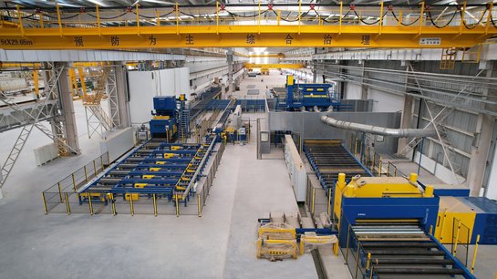
Ob Schiffswerft oder Stahl-Walzwerk, wenn es um Konservierungslinien geht, die besondere Anforderungen erfĂŒllen mĂŒssen, setzen Unternehmen weltweit auf die Kompetenz von Rösler. Basis sind das technische Know-how, die langjĂ€hrige Erfahrung und erfolgreich realisierte Referenzprojekte. Ein weiterer Aspekt sind die Projektteams aus Mitarbeitern der jeweiligen Rösler-Niederlassungen vor Ort und Spezialisten im Stammwerk Untermerzbach. Durch deren enge, globale Zusammenarbeit entstehen Lösungen mit maximalem Kundennutzen. C MCS – erfolgreicher Einstieg in neues Marktsegment China Merchants Cruise Shipbuilding (CMCS) ist einer der fĂŒhrenden Hersteller von Expeditionsschiffen, Schwimmplattformen und Schwimmladekranen, der die Konservierung der dafĂŒr benötigten Bleche und Profile bisher outsourcte. Dies sollte sich mit dem Ausbau der GeschĂ€ftstĂ€tigkeit um Passagier- und Kreuzfahrtschiffe Ă€ndern. Denn bei einem mittelgroßen Passagierschiff besteht alleine der Schiffsrohbau aus 25.000 Tonnen Stahl. Entsprechend wurde ein Partner fĂŒr den Aufbau einer leistungsfĂ€higen Konservierungslinie gesucht. Nach intensiver Sondierung des Marktes entschied sich das chinesische Unternehmen fĂŒr Rösler. Entscheidend dabei war die technische Umsetzung und Effizienz mehrerer Referenzprojekte in europĂ€ischen Werften, die Rösler als einziger Anbieter vorweisen konnte. Wettbewerbsvorteile durch vollautomatisiertes, verkettetes Konservieren Die individuell auf die Anforderungen von CMCS abgestimmte, 180 Meter lange Konservierungslösung besteht aus einer Blechlinie, der sogenannten Hauptlinie, und einer Profillinie, aus der die gestrahlten Profile in die Hauptlinie eingeschleust werden. Neben den beiden Rollenbahnstrahlanlagen mit optimal angepassten Gamma 400G- beziehungsweise Rutten Gamma 400 HD-Turbinen sind Richtanlagen fĂŒr die Profile und bis zu 12.000 mm langen Bleche, ein vollautomatisiertes Lackiersystem inklusive Farbversorgung sowie eine thermische Nachverbrennung integriert. SĂ€mtliche Anlagenkomponenten sind intelligent miteinander vernetzt und in das Produktionssystem der Werft eingebunden. Die Teile können dadurch von der Belade- bis zur Entnahmezone mit einer Vorschubgeschwindigkeit von 5 Metern pro Minute vollautomatisiert bearbeitet werden. Die kurzen Durchlaufzeiten bei hoher ProzessstabilitĂ€t und Reproduzierbarkeit sowie minimalem Personalaufwand tragen ebenso wie die robuste und verschleißoptimierte AusfĂŒhrung der Linie dazu bei, dass sich CMCS mit der Konservierungslinie einen Wettbewerbsvorsprung verschafft hat. Konservieren von Stahlblechen in neuer Dimension Einer der grĂ¶ĂŸten Hersteller von Stahl und Stahlprodukten mit BetriebsstĂ€tten in den USA, Kanada und Mexiko vergab den Auftrag fĂŒr die neue Konservierungslinie an Rösler. Hier waren die guten Erfahrungen mit einer vor Jahren an einen anderen Standort gelieferten Konservierungslinie ausschlaggebend dafĂŒr, dass sich das namhafte US-Unternehmen erneut fĂŒr eine Lösung von Rösler entschied. Die Dimensionen der zu bearbeitenden Stahlbleche mit 4.300 mm Breite, 18.000 mm LĂ€nge und einer MaterialstĂ€rke bis 200 mm machten eine angepasste AusfĂŒhrung der Konservierungslinie erforderlich. Belastbar bis 7 Tonnen pro laufendem Meter So ist die gesamte Linie, in der die Bleche vorgewĂ€rmt, gestrahlt, lackiert und getrocknet werden, auf eine Belastung von 7 Tonnen pro laufendem Meter ausgelegt. Üblich sind zwei bis drei Tonnen pro laufendem Meter. Die integrierte, 4.500 mm breite Rollenbahnstrahlanlage verfĂŒgt ĂŒber 10 Gamma 400G-Turbinen mit einer Antriebsleistung von jeweils 30 kW. Sie gewĂ€hrleisten, dass auf der gesamten Breite der Bleche bei einer Vorschubgeschwindigkeit von 4 m/min zuverlĂ€ssig ein homogenes Strahlergebnis erzielt wird und sorgen fĂŒr eine hohe ProduktivitĂ€t.

AM Solutions Delivers Post-Processing Solutions for Prototypes & Parts

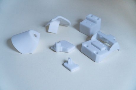
Knaus Tabbert AG is a leading manufacturer of recreational vehicles. The company’s innovative designs and powerful drive systems for motor homes, caravans, and panel trucks allow for safe, comfortable, and sustainable travel. At its German headquarters in Jandelsbrunn, Bavaria, Knaus Tabbert utilizes its comprehensive experience and know-how to continuously improve the materials and designs of its vehicles as well as new manufacturing technologies such as additive manufacturing. Seeking faster and less expensive post processing for its 3D printed prototypes, Knaus Tabbert turned to AM Solutions , a brand of The Rosler Group , to find a better way. Challenging Post-Processing From prototyping to production, Knaus Tabbert needed de-powdering and cleaning operations for additively manufactured work pieces. “On the one hand, we are using 3D printing technology for creating prototypes. On the other hand, we are also utilizing additive manufacturing for producing standard components in volume such as the bracket for an alarm system or the hinge mechanism for the swing-out shower stall,” said Mario Meszaros, Knaus Tabbert Development Engineer. De-powdering and cleaning of PA 12 polymer components produced by a powder-bed printing system were being done manually in a blast cabinet, producing highly erratic and inconsistent results as well as a lot of time and labor. The company wanted a more cost-effective and consistent automated alternative. Polymer parts used by Knaus Tabbert Comprehensive processing trials with different Knaus Tabbert components took place in the AM Solutions' Customer Experience Center . This division of The Rosler Group specializes in post-processing solutions for 3D printed components. After the conclusion of the highly successful processing trials, the customer chose the S1 shot blasting system . Perfect Cleaning & Quick Amortization The S1’s fully automatic operation delivers efficient finishing with absolute cleanliness. This shot blast machine was specifically developed for the post processing of plastic components produced with the powder-bed printing method. Featuring a plug-and-play design, the S1 is the only machine on the market to allow time-saving and cost-efficient de-powdering as well as surface smoothing and homogenization of 3D printed components in one single machine. All that is required is a simple change of the blast media , for example, from glass beads to plastic spheres. Equipped with a basket that rotates during the finishing operation and allows easy, ergonomic loading and unloading of the work pieces, the S1 offers fully automatic batch processing. Throughout the entire process—from loading and treatment to unloading—the basket remains in the machine housing. This, combined with a special door sealing system and antistatic system, prevents any powder spillage into the immediate surroundings. The control panel allows an easy and quick switch to manual operation without any retooling. “The fact that after surprisingly short cycle times the components came out of the machine perfectly clean and without any powder residues was very impressive,” Meszaros said. “With the underlying operating data, I prepared a ROI calculation. The results quickly convinced our management that, even with only three print jobs per week in the S1, we will achieve a return on our investment after roughly two years.” Since it is safe to assume that the quantity of 3D printed components will increase significantly, Meszaros said he expects that the amortization period will be drastically reduced as the S1 is used more extensively. Process Stability & Operational Safety In addition to excellent processing results and rapid amortization, the S1’s standard version also features a system that automatically monitors and records all relevant process parameters. The integrated blast media cleaning and recycling system drives high process stability by ensuring that media is always available in perfect condition no matter what type is utilized. The explosion-protected design of the shot blast machine with ATEX-compliant motors and valves provides additional peace of mind and safety. “I am absolutely convinced that the simple, effective, and efficient post-processing possibilities of the S1 will further promote the use of additive manufacturing in our company,” Meszaros said. David Soldan, Head of AM Solutions, agreed, adding that Rosler and AM Solutions provide finishing solutions to a variety of industries . “More and more companies from different industries are choosing the S1 for post processing their 3D printed components,” Soldan said. “This confirmation of our product strategy shows that our 3D post-processing products are in full compliance with the requirements of the market.” The Rosler Way “Finding a better way
” is more than a motto at Rosler; it’s our mission and why AM Solutions exists. With more than 80 years of experience and a portfolio containing more than 15,000 equipment and consumable products, solving challenges is what we do. Contact us today to discuss your additive manufacturing post-processing challenges!
Wendekammer-Strahlanlage RWK

Wir bauen mit am Auto der Zukunft

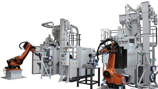
Integrierbare Wendekammer-Strahlanlage ermöglicht Teilebearbeitung im Fertigungstakt Der Wandel in der Automobilindustrie schreitet immer weiter voran. Die europĂ€ische Union hat Anfang Juni beschlossen, den Verkauf von Verbrennermotoren ab 2035 zu verbieten. Die Zustimmung der einzelnen EU-Staaten vorausgesetzt dĂŒrfen dann nur noch Elektroautos oder vergleichbar klimaneutrale Fahrzeugsysteme verkauft werden. Um deren Reichweite weiter zu steigern werden die Autobauer in Zukunft noch stĂ€rker auf Leichtbauteile setzten. Doch schon seit Jahren werden Leichbaukomponenten immer stĂ€rker im Automobilbau eingesetzt, etwa um die Emissionen von klassischen Verbrennermotoren zu verringern. In Leichtbauweise werden unter anderem StatortrĂ€ger, GehĂ€use sowie Bauteile fĂŒr die Antriebstechnik, aber auch Achs- und Radaufnahmen hergestellt. Diese entstehen im Sand-, Druck oder Spritzgussverfahren. Anschließend mĂŒssen die Teile feinentsandet, entgratet und ihre OberflĂ€chen homogenisiert werden. DafĂŒr entwickeln unsere Strahltechnik-Experten bei Rösler maßgeschneiderte Lösungen. Eine davon ist unsere kompakte Wendekammer-Strahlanlage mit automatisiertem Teilehandling. Sie wurde so entwickelt, dass sie sich platzsparend in kompakte Fertigungslinien integrieren lĂ€sst. Das ermöglicht Teilebearbeitung im Fertigungstakt – effizient, prozessorientiert und innovativ. Ihre Vorteile der Wendekammer-Strahlanlage RWK: VerkĂŒrzte Taktzeit durch zeitgleichen Strahl- sowie Be- und Entladevorgang Optimal fĂŒr die Integration in bestehende Fertigungslinien Prozesssichere Aufnahme der Bauteile durch integrierte pneumatische Klemmeinheit Hohe StrahlintensitĂ€t dank Hochleistungsturbinen Strahlkammer aus Manganstahl mit zusĂ€tzlich auswechselbaren Platten

Mass Finishing Work Piece Handling Series, Part 1 – Selecting the Best Work Piece/Media Separation Method

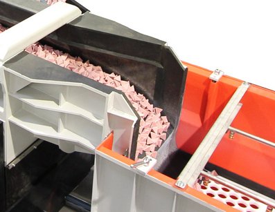
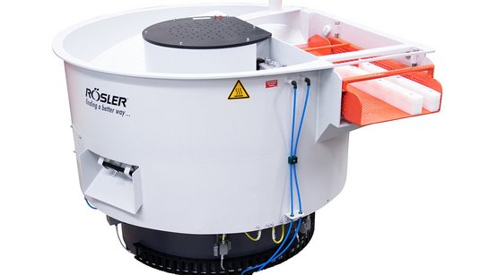
One of the first considerations in finishing process development is the ability to effectively separate mass finishing media from the work pieces. If separation cannot be achieved, the process will not be viable. Signs of inadequate separation may include the need for too much manual intervention, lodged media causing downstream process issues, failure to meet finishing standards, or even product recalls. For processes that do not require work pieces to be firmly mounted to fixtures in the machine, components and media loosely tumble in mass finishing processing bowls and troughs to achieve the desired finishing result. While this interaction is encouraged during processing, swift and precise media separation is crucial before work pieces move onto the next process step. Rosler has more than 80 years of experience designing mass finishing machines and supplying consumables. Our expertise can help develop the best separation method and settings for your unique combination of finishing, work pieces, and media. Separation Objectives If not properly removed from work pieces, media carried out of the machine can cause disastrous results in automated, downstream manufacturing operations such as machining, assembly, painting, etc. The manner in which media and work pieces are separated matters as well. The separation stage must not be too aggressive, as it could damage the finished work pieces with nicking and scratching if not carefully calibrated. Media and work pieces exit the machine outlet and pass over a polyethylene screen with round holes for external separation Separation must also take place in the shortest possible time to avoid costly extensions of the overall cycle time. The separation process should not require any support by the machine operator such as manually holding back the media/work piece mix on the separation screen. Separation Speeds While all machine types must meet the aforementioned separation objectives, some types require extra adjustments for vibratory motor speeds to aid the separation process within the machine. Where possible, separation is done in the finishing machine. This reduces the need for media handling, as the media remains in the machine and the parts are separated via built-in separation screens. Reducing the machine speed in rotary vibrators , long radius machines, and vibratory dryers after the higher intensity processing cycle provides more effective separation and minimizes part-on-part damage during the parts unloading step. Rosler rotary vibrator with internal separation screen Machines that require unloading the media/part mix from the machine at the end of the finishing process usually use external screening systems to separate the parts from the media. The external screening system has its own vibratory drive system that can be set and adjusted to maximize the screening speed while providing gentle part transportation. Rosler rotary vibrator with internal separation screen In either case, it is very important to select the correct screen type and hole size. Holes that are too small may cause media carry‐out while holes that are too large might cause work pieces to lodge in the screen or even fall back into the machine. The screen deck length must also be carefully considered. Methods of Separation In mass finishing, screen and magnetic methods of separation are most common. Separation Screens Available in a wide selection of hole sizes and shapes, separation screens are made of a variety of materials. Screen types include (top, from left) polyethylene screens with round or oblong holes, (middle) wire mesh screens coated with polyurethane or made from steel, and (bottom) bar screens made from steel or polyethylene Rosler offers numerous screen options, including: Polyethylene screens with round or oblong holes. Wire mesh screens coated with polyurethane or made from steel. Bar screens made from steel or polyethylene. Magnetic Separators When screen separation is difficult or even impossible, magnetic separators are a good alternative. For example, when the work pieces and the media have a similar shape or are the same size, magnetic separation is an excellent option. The use of magnetic separators requires that work pieces are ferrous and attracted by a magnet. These systems can be configured with a drum or belt as well as demagnetizing zones. Rosler magnetic drum separator Rosler magnetic belt separator Updates for Existing Systems Consult with your supplier to learn about the available separation options for the mass finishing machine you are using or intend to use. Available equipment updates may include: Frequency inverters enabling you to vary the motor’s speed. Most vibratory motors run at two speeds; namely 1,800 RPM (4‐pole mode) or 1,200 (6‐pole mode) by default. Installation of different screens utilizing different materials and hole sizes and shapes. Magnetic drum or belt separators. Regardless of the upgrade, ask your supplier to run a test processing trial before installation to ensure the change is satisfactory. Rosler offers free testing in our global Customer Experience Centers . The Rosler Way Decades of experience and ability to design, service, and maintain machines as well as the consumables and accessories to get the finish you require make Rosler a well-rounded surface finishing expert. Contact us to discuss your mass finishing and work piece handling needs. The complete Mass Finishing Work Piece Series includes: Part 1 – Selecting the Best Work Piece/Media Separation Method . Part 2 – Preventing Drop Height Damage . Part 3 – Maintaining Wear Linings .

Mass Finishing Machine Settings Series, Part 2 – Determine Imbalance Weight Settings for Consistent Results

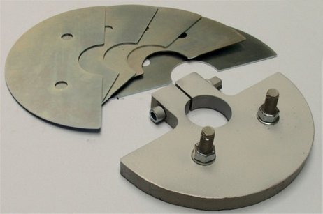
Specific mass finishing applications are developed through processing trials. Once defined, users should not deviate from the determined machine settings unless necessitated by work piece or process changes. Rosler partners with clients to provide testing in our global Customer Experience Centers to demonstrate our capabilities on a specific work piece and to calibrate machine settings. Determining the exact machine settings requires considering and testing multiple factors. Vibratory Systems The most common drive systems in mass finishing are vibratory. This refers to actual finishing machines such as rotary , tub , and linear continuous flow vibrators as well as auxiliary equipment like screening systems, vibratory conveyors, buffers, etc. In all of these cases, the speed of the vibratory motor or the electric motor driving the imbalance unit(s) may have to be adjusted as well as the setting of the imbalance weights. Vibratory weight plates The angle between the upper and lower imbalance weights determines the movement of the media and work piece mix within the machine. The number (mass) of imbalance weights determines the processing intensity (amplitude). More weights produce higher intensity while fewer weights deliver lower intensity. Vibratory motor diagram Setting Imbalance Weight s The movement of the media/work piece mix is always opposite to the motor direction. Typically, the motor runs clockwise and the media/work piece mix runs counter clockwise. In some instances, the motor can run clockwise and counterclockwise including the Rosler “R” machines and gate clearing in Rosler “Euro” machines. Half-circle metal plate weights on the top and bottom of the motor must be positioned with respect to each other. For a basic setting, the bottom weight plate must be turned 90 degrees forward of the top weight plate, in a basic setting. Imbalance weights locations and settings within a vibratory motor When setting imbalance weights, it is important to understand the impact of changes. For example, increasing the lead angle will make the media/work piece mix travel around the work bowl faster. Decreasing the lead angle will have the opposite effect, slowing movement. Typical lead angles range from 70 to 120° and can be observed by checking the gauge on the top of the motor shaft. Vibratory motor lead angle gauge Within the imbalance weights, the top weight controls the travel speed of the media/work piece mix around the work bowl. Adding additional weights to the top will increase the travel speed while decreasing the spiral speed in the work bowl. The top imbalance weight controls media and workpiece speed around the work bowl as represented by the red arrow while the bottom imbalance weight controls the spiraling speed of the work bowl contents. The bottom weight controls the spiral speed of the media/work piece mix in the work bowl. Conversely to the top weight, adding additional weights to the bottom will increase the spiral speed but also decrease the travel speed around the work bowl. Action Points Regularly checking a mass finishing machine’s settings including motor speed(s), setting of imbalance weights, work station angles, etc. to ensure they are as initially established will produce better results and protect the systems ROI. A vibrocope sticker on the work bowl allows for a quick check of the processing intensity. Additional information can be found in our Using Vibrascope to Measure Amplitude v. Frequency in Vibratory Bowls blog post. Virboscope sticker Additionally, if repairs require drive motors to be disconnected, make sure that they are rewired correctly and are not running in the wrong direction. If the machine settings must be changed, carefully follow the instructions in your operator’s manual or consult the manufacturer for assistance. If not already integrated, installation of a frequency inverter for precise setting of the drive speed of your machine may be available as an upgrade, providing additional control and oversight. The Rosler Way Rosler goes beyond developing mass finishing machines to provide operational insight and guidance for the lifetime of our machines as well as consumables and service . Contact us to discuss your needs and our capabilities. The Mass Finishing Machine Settings Series also includes Part 1 – Improve Machine Function with Proactive and Responsive Observation, Calibration .

Customer Experience Centers Offer Free Surface Finishing Insight & Solutions

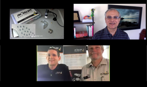
During more than 80 years in business, the Rosler team has gained extensive experience in shot blasting and mass finishing for a variety of industries . In addition to the machinery and consumables we provide, our Customer Experience Centers enable us to demonstrate Rosler’s expertise by processing your samples with settings and requirements tailored to your needs. Sending your work pieces to one of our 11 test centers around the world is an important step in achieving the perfect surface finishing process. Learn what to expect from Rosler’s Customer Experience Centers and get the most out of your partnership with Rosler from Sales Representative and Interim Product Manager of Turbine Blast Equipment Zack Murray and Mass Finishing Product Manager Michael Salyers. What to Expect as a Customer To achieve optimal processing results, we carry out sample processing step-by-step. With an emphasis on finding a better way, our process includes: A joint kick-off meeting (in-person or virtually) between your team and Rosler experts to set the processing objective. Determination of the process technology. Sample processing. Appraisal by Rosler shot blasting or mass finishing experts. In some cases, both. Creation of detailed test and measurement reports. An opportunity for you to evaluate the results and a final meeting. Salyers, a mass finishing expert with four years of experience at Rosler, describes the sampling process as collaborative and informative. “The customer gets the chance to meet all of the key players involved in the project. They have the opportunity to ask any questions they may have, review the equipment available, and discuss the pros and cons of each,” he said. “As a team, we review the customer’s parts, goals, and expectations. Based on many years of experience, our team will consider each factor involved with finishing the part, select the most appropriate machine, media, and compound, and then run test trials in order to reach the stated goal.” Whether you are in search of a mass finishing or shot blasting system, you can expect a team who will listen to your desires, uncover and discuss your pain points, and then develop a solution that best fits your goals, Salyers said. Murray, a shot blasting expert with nearly nine years of experience, agreed but said the shot blasting sampling process typically starts with more options already predetermined. “A large majority of the time, customers already know what shot blasting media they are going to be using—either because they are already using it in a different machine, a sisterplant of theirs is using it for similar applications, or an upstream application is currently outsourced using that media,” he said, “Therefore, the only things that need to be verified are time cycles for batch or single part processing applications or throughput speeds for continuous throughput applications.” Rosler CEO Bernhard Kerschbaum (bottom left) and Customer Experience Center Process Expert Jim Kellay (bottom right) meet virtually with a customer to discuss a test batch and demonstrate Rosler’s capabilities without the need for an in-person meeting. The typical testing experience does not even necessitate the customer’s presence on-site, Murray said. Testing can be accomplished by the customer sending sample work pieces to Rosler which are then processed with different cycle times or throughput speeds and sent back to the customer for evaluation. “For the relatively rare case wherein the customer is in need of our support for media selection and th eprocess needs are special enough that we don’t have an ‘off-the-shelf’ solution ready based on previous experience, Rosler tries to have the customer visit our facility for the testing,” Murray said. “We do an initial round of testing in our manual air blast or wet blast cabinets using a small cut of the part for larger parts or a small batch of the parts for smaller parts so that we can quickly change out the media to show the results of several materials and/or sizes of media. Once the customer has verified which media gives them the finish they are looking for, we do a separate test to verify time cycles orthroughput speeds.” Preparing for Testing While testing in our Customer Experience Centers is free of charge to prospective and current customers, Rosler understands that your time is valuable. Gathering the right information prior to testing can help expedite your test trials and enable us to develop the exact system for your needs more quickly so you can implement changes or plan for system upgrade investments sooner rather than later. Gathering information for testing typically begins with a one-page initial inquiry questionnaire specific to mass finishing or shot blasting. Both versions contain questions related to processing objectives, final surface quality, work piece conditions and specifications, desired processing modes, reason for investment, project budget, and desired timeline. Specific to the type of surface finishing sought, each questionnaire also addresses current systems in use and more process-specific information. Rosler Customer Experience Center Process Expert Jim Kellay conducts a virtual test trial review with a customer. “Our goal is to create a collaborative process,” Salyers said. “The more information a customer can provide regarding their problems and goals, the more effective solution we can develop. “No two projects are the same. There is no magic bullet or media for every part. Each part must be considered individually before a comprehensive process can be developed.” Rosler’s ability to communicate the potential and limitations of shot blasting and mass finishing for specific customer processes relies on understanding the customer’s initial work piece condition and end goal, all finishing steps utilized, and productivity metrics sought. “Communication is the key in identifying unrealistic expectations as well as identifying innovative solutions,” Salyers said. “Fully understanding the customer’s needs and goals in the beginning helps us achieve maximum results for them.” Visual inspection of knee femorals after tested processing in Rosler’s United States-based Customer Experience Center for the desired surface finish. The Rosler Way “Finding a better way
” is more than a motto at Rosler; it’s our mission. With more than 80 years of experience and a portfolio containing more than 15,000 equipment and consumable products, solving challenges is what we do. Contact us today to get our Customer Experience Center to work developing a solution for your surface finishing challenges!

Dutch Equipment Manufacturer Increases Flexibility with Automatic Shot Blasting

Blast cleaning is uniquely capable and efficient at delivering the pre-coating surface preparation required for components that must be able to withstand severe ambient conditions including heavy equipment for construction and mining, agricultural machinery, transportation and material handling equipment, and railway equipment and rolling stock. When Dutch equipment manufacturer Delwi Groenink sought a better solution for prepping its various steel weldments for painting, the company enlarged its manufacturing depth with a new continuous hanger shot blast machine from Rosler . The Situation Based in Enschede, Netherlands, the company designs and produces numerous products including placement systems for container pads. Its customers largely work within the material handling, offshore, and transportation sectors. Prior to the new system, pre-treatment of steel components utilized various external job shops for manual shot blasting in labor-intensive blast rooms and paint booths. In addition to complex logistics, the process was also time-consuming. The Solution To accelerate the manufacturing process and become more flexible, the company decided to bring these processes in-house and took over the job shops including their staff. To further optimize operations, Delwi Groenink invested in a modern shot blasting machine , which was placed in a new building adjacent to the painting facility. The company selected Rosler’s continuous hanger shot blast machine RHBD 27/32-K after shot blasting trials with Delwi Groenink components in our Customer Experience Center in addition to demonstration of similar Rosler systems in the field, and Rosler’s technical service in the Benelux countries. The Specifications The RHBD-K is designed for continuous processing of single components and batches of multiple work pieces with dimensions up to 10 ft (3 m) long, 10 ft (3 m) wide, and 40 ft (12 m) long. The blast chamber is manufactured from manganese steel. Easy-to-exchange, gap-free manganese liners are also added in areas exposed to the blast stream for added protection. The required high blasting intensity is generated by 16 Gamma 400 G turbines , each with an installed power of 11 kW. The turbines are arranged vertically in two rows on the left and right wall of the blast chamber, with the two rows being somewhat offset from each other. Combined, the turbines throw approximately 5,000 lb (2,240 kg) of blast media per minute. This ensures excellent blast coverage and uniform preparation of all surfaces. The special “Y” design of the throwing blades and the optimized media transfer in these Rosler high-performance turbines allow a highly fluidized media movement with little or no turbulence. Compared to conventional turbines of similar sizes, the resulting higher throwing and impact speeds produce a 15- to 20-percent-higher blast performance. Blasting efficiency is further improved by the concentrated blast pattern. Moreover, both sides of the throwing blades can be utilized resulting in a doubling of the uptime of the throwing blades. All these technical features, along with the fact that the blades can be exchanged within only seven minutes, convinced the customer. The Process Once a steel weldment has been transferred to the transport truss, the RHBD-K recognizes that a component is ready to be blasted and transports it into the entry chamber. As soon as a sensor monitoring the front area of the blast machine signals that no people are present, the double-leaf door closes automatically. According to the part-specific treatment program, all or some turbines then start up and blasting begins in the blast chamber. This blasting intensity can be adjusted with frequency inverters. After completion of the blast cycle, the work piece is transported into the exit chamber, media flow is interrupted with shell valves, and turbines turn off allowing the operator to manually remove blast media and dust from the work piece. Once finished, the operator leaves the exit chamber and signals another sensor to initiate and open the double-leaf doors so a transport truss can remove the work piece from the machine. Designed to handle a media throughput of around 2.5 metric tons per minute, the media recycling and cleaning system includes an elevator, cross auger, and air wash separator. The Rosler Way “Finding a better way
” is more than a motto at Rosler; it’s our mission. With more than 80 years of experience and a portfolio containing more than 15,000 equipment and consumable products, solving challenges is what we do. Contact us today to discuss your surface finishing goals and how we can deliver improvements!